Cookstove fire extinguishing system

a fire extinguishing system and automatic action technology, applied in the field of cooking stove fire extinguishing systems, can solve the problems of high cost, complex known shutoff arrangement, and high installation and operation costs, and achieve the effect of low installation cost and high reliability

Inactive Publication Date: 2010-01-07
REYNOLDS JOE DALE
View PDF21 Cites 10 Cited by
  • Summary
  • Abstract
  • Description
  • Claims
  • Application Information

AI Technical Summary

Benefits of technology

[0027]There is a need in the art for a fire extinguishing system which will satisfy the needs of those kitchen type stoves that do not have range hoods and to provide a system that will be of low cost to install, have high reliability, and not require professional services in its installation. Accordingly, several objects and advantages of the present invention are:
[0028](a) to provide a fire extinguishing system for a cooking type stove that is fail safe;
[0029](b) to provide a fire extinguishing system that can be installed without the need for professional services;
[0030](c) to provide a fire extinguishing system that will be versatile and allow installation of components in other than a single type of application;
[0031](d) to provide a fire extinguishing system that can interface with a number of different extinguisher nozzles to meet differing requirements;
[0032](e) to provide a fire extinguishing system in which its cooking gas connection to a stove is a simple screw in pipe connection.

Problems solved by technology

Even the smallest prior art device installed in a range hood leaves much to be desired in appearance due to the wires, pipes extinguishing nozzles and tanks that can be easily seen by persons near the stove and over time collect unsightly grease and dirt and are difficult to clean.
Known shutoff arrangements are generally complex, expensive, and present added components subject to faults and errors in installation and operation.
Such devices quite often require professional services such as electricians for their installation, thus this also contributes to onsite installation time and expense.
This method was later seen as impractical and was later dropped in a succeeding patent, Mikulec U.S. Pat. No. 5,899,927 (1999), for a much more complicated interruption method.
Both means of operation require considerable on site labor for both installation, adjustment, and some components could fail during an emergency.
This does not really solve the problem of a grease fire for water is the wrong material to use in such an instance and further the system is intended for a large liquid reservoir system to utilize the cycling on and off.
If the home owner does not check the battery system regularly the system could easily fail to shut off the stove energy source in a fire emergency.
This system is totally dependent on electrical power and is subject to many faults and consequently is not fail safe.
In applying the system to either a range hood or beneath the burner Banner uses electrically operated valves for discharge of the fire suppressant beneath the burners, which might prove less than effective.
The system utilizes a spray nozzle which is connected to the building water supply and is usually considered to be the wrong material to fight a grease fire.
Further the spray nozzle has to spray material of a viscosity of one, which is probably water and the nozzle is a cooling spray nozzle of limited capacity usually associated with cooling back porches.
These prior art devices have the disadvantage of being designed only for under or within a range hood even though today thousands of kitchens are designed with a microwave oven with exhaust in place of the range hood.
Some require taught wires that require some experience to install and are in a position under a range hood to collect grease and dirt and with such pipes, wires, and other paraphernalia will be difficult to clean.
Others rely on electronics for acoustically operating the disruption in electricity or gas and are inherently less reliable than a fail safe system.
It must be kept in mind that the average home owner will seldom think of maintenance for such a system and therefore systems of such design can fail long before they are needed in an emergency.

Method used


Image

  • Cookstove fire extinguishing system
  • Cookstove fire extinguishing system
  • Cookstove fire extinguishing system

Examples


Embodiment Construction

[0044]The preferred exemplary embodiments of the invention are illustrated in FIG. 1 through FIG. 4E wherein like numerals represent like parts. In the drawings, closely related figures have the same number but different alphabetic suffixes. Each segment of the system is discussed in detail individually.

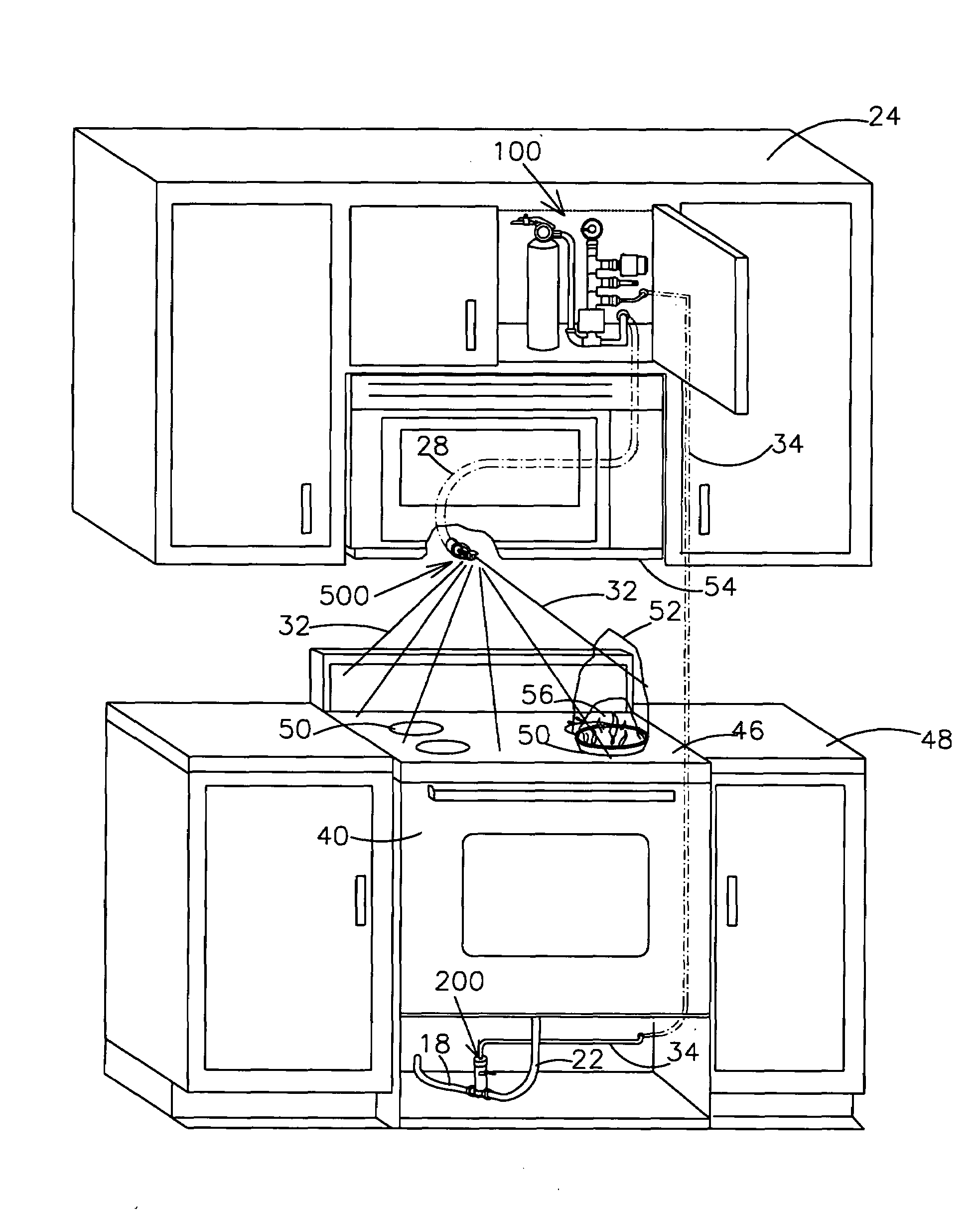
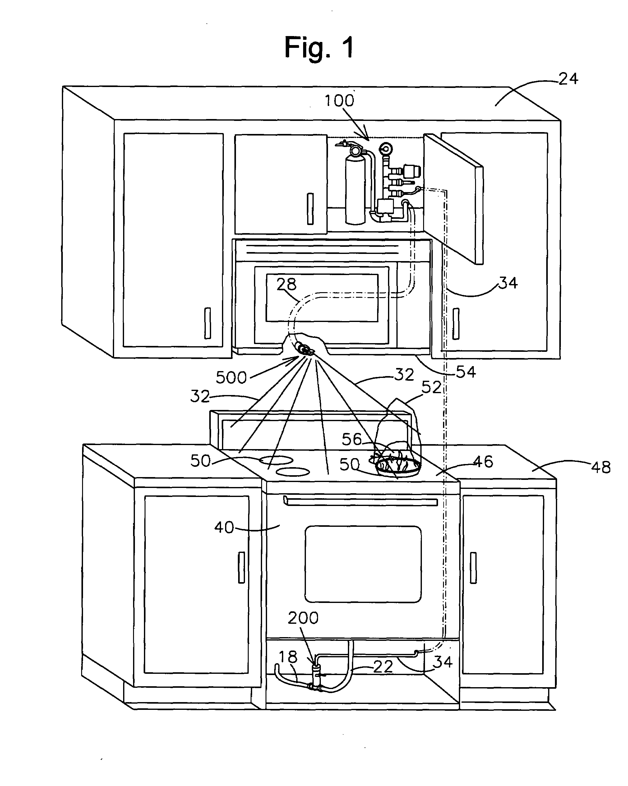
[0045]A preferred embodiment of the complete system in FIG. 1 for application to a gas stove 40 without a range hood but with a microwave oven 54 is illustrated with the control unit 100 located in a cabinet 24 and connected by high pressure hose or pipe 34 to a pressure operated gas cut off valve 200 which receives the flammable gas by means of a supply line 18 and passes the gas through to the stove burners 50 by means of a supply line 22.

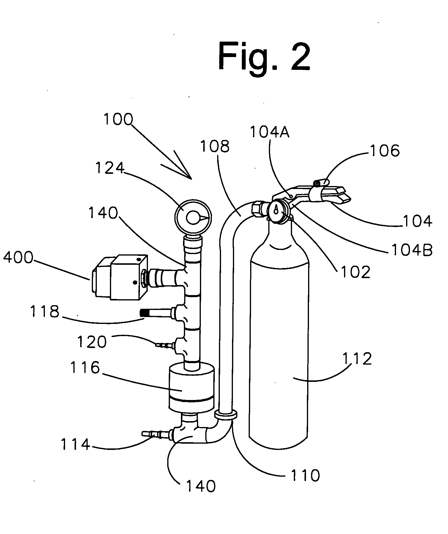
[0046]Fire suppressant under pressure is incorporated in the said control unit that supplies pressurized gas and extinguishment to a thermally actuated spray head 500. The said control unit may be mounted in a cabinet over the said stove 24FIG. 1 ...


PUM


Abstract

An improved fire protection system that is of fail safe design for kitchen stoves and other applications utilizing gas for generating heat and in which a fire condition such as a skillet of grease becomes ignited. Said system is activated thermally to release a quantity of fire suppressant material onto the top of the stove quenching the fire while simultaneously cutting off the cooking gas. The system utilizes a reservoir containing the fire suppressant under pressure with a hose or pipe connected to one or more thermally activated spray heads. A second hose or pipe is connected to a pneumatically operated gas cut off valve. The activation of the thermally activated spray head or heads exhausts the pneumatic pressure of the reservoir thereby causing the gas cut off valve to close against the cooking gas.

Description

CROSS REFERENCE TO RELATED APPLICATIONS[0001]This is a division of application Ser. No: 11,647,055 Filing Date: Dec. 27, 2006 Art Unit 3752FEDERALLY SPONSORED RESEARCH[0002]Not ApplicableSEQUENCE LISTING OR PROGRAMS[0003]Not ApplicableBACKGROUND OF THE INVENTION[0004]1. Field of Invention[0005]This invention relates to an automatically actuated totally pressurized fire extinguishing system to fit all near wall kitchen stoves with or without a range hood. The invention includes a unique means of automatic shutoff of the heating gas to the stove.[0006]2. Prior Art[0007]The use of automatically activated fire extinguishing devices for cooking stoves is known. Such devices provide a source of fire extinguishing compound to be released on to a stove surface in the event of a fire which occurs during use of the appliance. Virtually all prior art devices are designed and made only for installation within a range hood though preference today often calls for a microwave oven mounted over the...

Claims


Application Information

Patent Timeline
Patent Type & Authority Applications(United States)
IPC IPC(8): A62C3/00
CPCA62C3/006F24C15/2021
Inventor REYNOLDS, JOE DALE
Owner REYNOLDS JOE DALE
Why Eureka
Try Eureka