Communications system and communications lighting apparatus

a communication system and lighting apparatus technology, applied in the field of communication system and communications lighting apparatus, can solve the problems of system not fully utilizing lighting apparatus, light it emits not being utilized in optical communication, information transmitted and received is limited to data, etc., to achieve high speed, low cost, and high precision

Active Publication Date: 2011-10-13
SONY CORP
View PDF3 Cites 1 Cited by
  • Summary
  • Abstract
  • Description
  • Claims
  • Application Information

AI Technical Summary

Benefits of technology

[0014]The communications lighting apparatus of this invention can be used in place of a conventional lighting apparatus. Thus, it can be installed at low cost by using the existing lighting infrastructure.
[0015]Moreover, the communications lighting apparatus of the invention can transmit information at high speed and high precision. This is because the second light source unit comprises light sources that emit light beams of different wavelengths or a combination of an end-plane emission semiconductor laser, a vertical-plane emission semiconductor laser, and a quantum-cascade semiconductor layer. The communications lighting apparatus can therefore transmit information at high speed and high precision. In addition, the second light source unit can be small.

Problems solved by technology

The system disclosed in Japanese Patent No. 2668793, however, is designed for limited use only, for example in plants.
The information transmitted and received is limited to the data for controlling a robot.
This system does not fully utilize lighting apparatuses that are light-emitting means widely and commonly used.
The light they emit is not utilized in optical communication, however.
This means that the existing lighting infrastructure is not fully used in our daily life.

Method used


Image

  • Communications system and communications lighting apparatus
  • Communications system and communications lighting apparatus
  • Communications system and communications lighting apparatus

Examples


Embodiment Construction

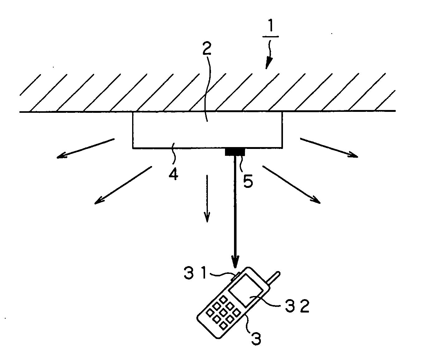
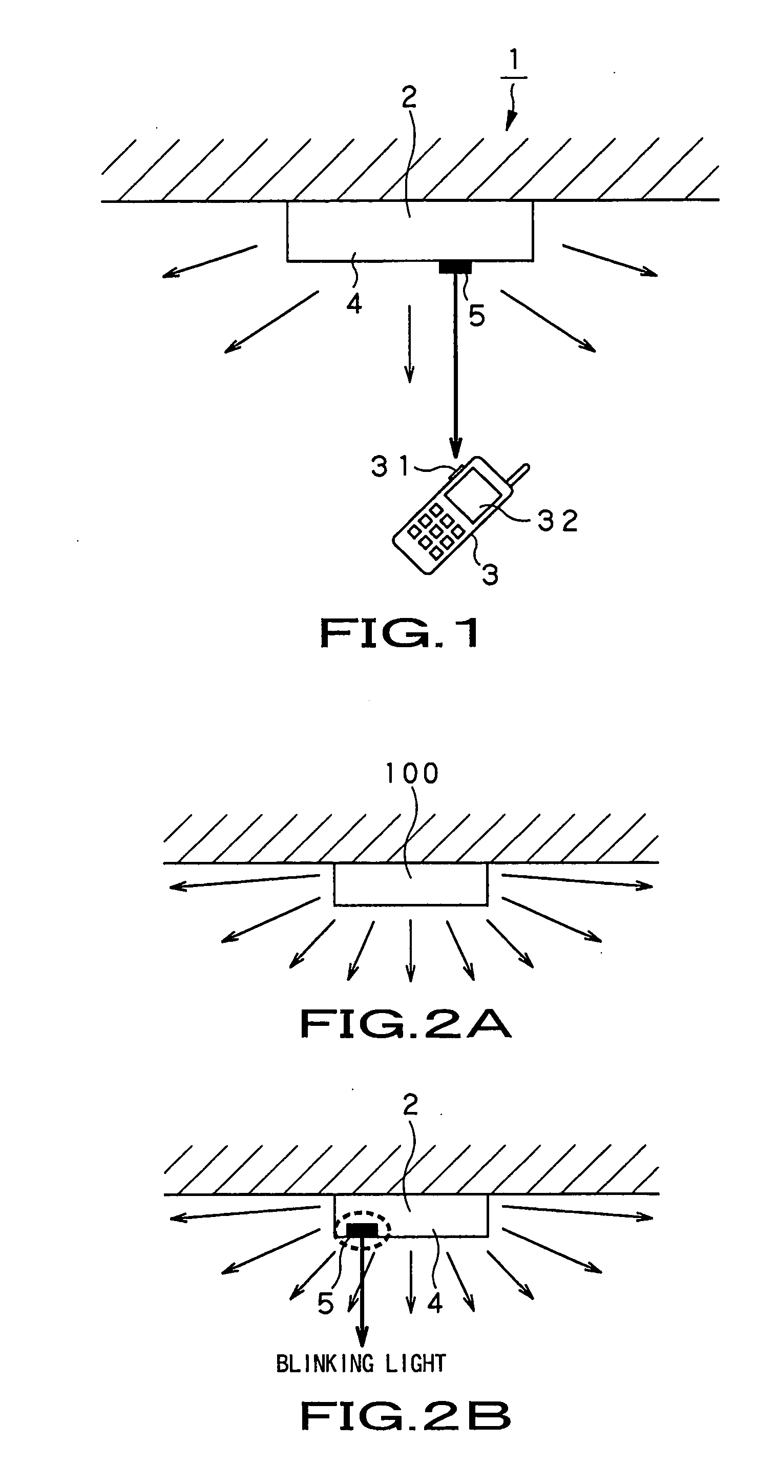
[0028]A lighting communications system 1 according to the present invention will be described. The lighting communications system 1 utilizes a lighting apparatus, which is an element of the lighting infrastructure, to accomplish optical communication. In system 1, the lighting apparatus performs not only its essential function of providing people with a “view field,” but also an additional function of achieving optical communication.

[0029]FIG. 1 shows a lighting communications system 1 according to this invention. The lighting communications system 1 comprises an optical-information transmitting, lighting apparatus 2 and a mobile terminal 3. The lighting apparatus 2 can transmit optical information in the form of an optical signal. The mobile terminal 3 can receive the optical signal that the lighting apparatus 2 has emitted.

[0030]The mobile terminal 3 has a light-receiving unit 31 and a display unit 32. The light-receiving unit 31 can receive the optical signal transmitted from the...


PUM


Abstract

An optical-information transmitting, lighting apparatus 2 is installed in a place where a lighting apparatus of the existing type for applying light generally used is provided. The lighting apparatus 2 comprises an illumination light source 4 for applying light and an information-transmitting unit 5 for transmitting optical information. A person who may receive information from the lighting apparatus 2 has a mobile terminal 3, which receives the optical information transmitted from the information-transmitting unit 5. Since the lighting apparatus of the existing type is widely used in our living space. Hence, the optical-information transmitting, lighting apparatus 2 can convert every place where an existing type lighting apparatus is used, into an optical communications space.

Description

CROSS REFERENCES TO RELATED APPLICATIONS[0001]The present invention is a Continuation of application Ser. No. 10 / 809,432, filed Mar. 26, 2004, which contains subject matter related to Japanese Patent Application JP 2003-103425 filed in the Japanese Patent Office on Apr. 7, 2003, the entire contents of which being incorporated herein by references.BACKGROUND OF THE INVENTION[0002]1. Field of the Invention[0003]The present invention relates to a communications system and a communications lighting apparatus, each using illumination light to accomplish optical communication.[0004]2. Description of the Related Art[0005]Recent years have seen a fast progress in broadband, wired or wireless communications technology as the increase in amount of personal use information. To be more specific, communication service using existing telephone lines, such as ADSL (Asymmetric Digital Subscriber Line), has come into use. Communication can therefore be achieved at high speed and low cost. The next-g...

Claims


Application Information

Patent Timeline
Patent Type & Authority Applications(United States)
IPC IPC(8): H04B10/02H04B10/00H04B10/11H04B10/112
CPCH04B10/116H04B10/1149
Inventor OKANO, NOBUKATAWATANABE, YOSHIAKIMITOMO, JUGOHINO, TOMONORINARUI, HIRONOBU
Owner SONY CORP
Why Eureka
Try Eureka