Method for refrigerant and oil collecting operation and refrigerant and oil collection controller

a technology of controller, which is applied in the direction of refrigeration machines, compression machines with reversible cycles, corrosion prevention, etc., can solve the problems of affecting the operation of the refrigerant and oil collection controller, the existence of contaminants of the residual refrigerating machine oil, and the easy precipitation of condensation

Inactive Publication Date: 2007-02-20
DAIKIN IND LTD
View PDF16 Cites 2 Cited by
  • Summary
  • Abstract
  • Description
  • Claims
  • Application Information

AI Technical Summary

Benefits of technology

[0007]This invention has been made to remove the aforementioned conventional drawbacks and has the object of providing a refrigerant and oil collection operating method and refrigerant and oil collection control device, which is able to inexpensively secure cleanliness in the existing interconnecting piping and therefore able to install a new air conditioner at low cost.

Problems solved by technology

Moreover, the HFC-based refrigerant, which structurally has a strong polarity, has the properties that it dissolves neither nonpolar sludge nor contaminant (mineral oil and the like) and tends to easily precipitate them in the condensed liquid refrigerant.
The precipitate adheres to the cramped portions of a capillary tube, an expansion valve and the like, causing clogging.
This consequently causes abnormal stop due to the discharge temperature rise of the compressor and the compressor failure due to the malfunction of the expansion valve, and therefore, it is required to devise sufficient countermeasures.
However, the synthetic oil, which has a strong polarity, therefore has the property that it easily dissolves the residual impurities other than the refrigerating machine oil and the refrigerant.
Therefore, in a refrigeration apparatus that employs a synthetic oil as a refrigerating machine oil, clogging with sludge and the like after the evaporation of the refrigerant tends to easily occur in a decompression mechanism constructed of an electric expansion valve, and this easily causes a problem that abnormality occurs in the refrigeration cycle.
In the case where the refrigerant piping is laid in walls as described above, the existence of the contaminants of the residual refrigerating machine oil and so on in the existing interconnecting piping emerges as a problem when installing a new air conditioner by removing the existing air conditioner.
However, the conventional method of cleaning the existing interconnecting piping, as described above, has a problem that it needs much labor and time and needs a considerable amount of cost for the installation of a new air conditioner.

Method used


Image

  • Method for refrigerant and oil collecting operation and refrigerant and oil collection controller
  • Method for refrigerant and oil collecting operation and refrigerant and oil collection controller
  • Method for refrigerant and oil collecting operation and refrigerant and oil collection controller

Examples


first embodiment

(First Embodiment)

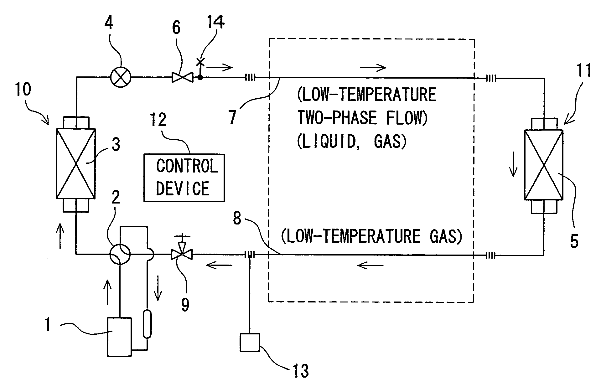
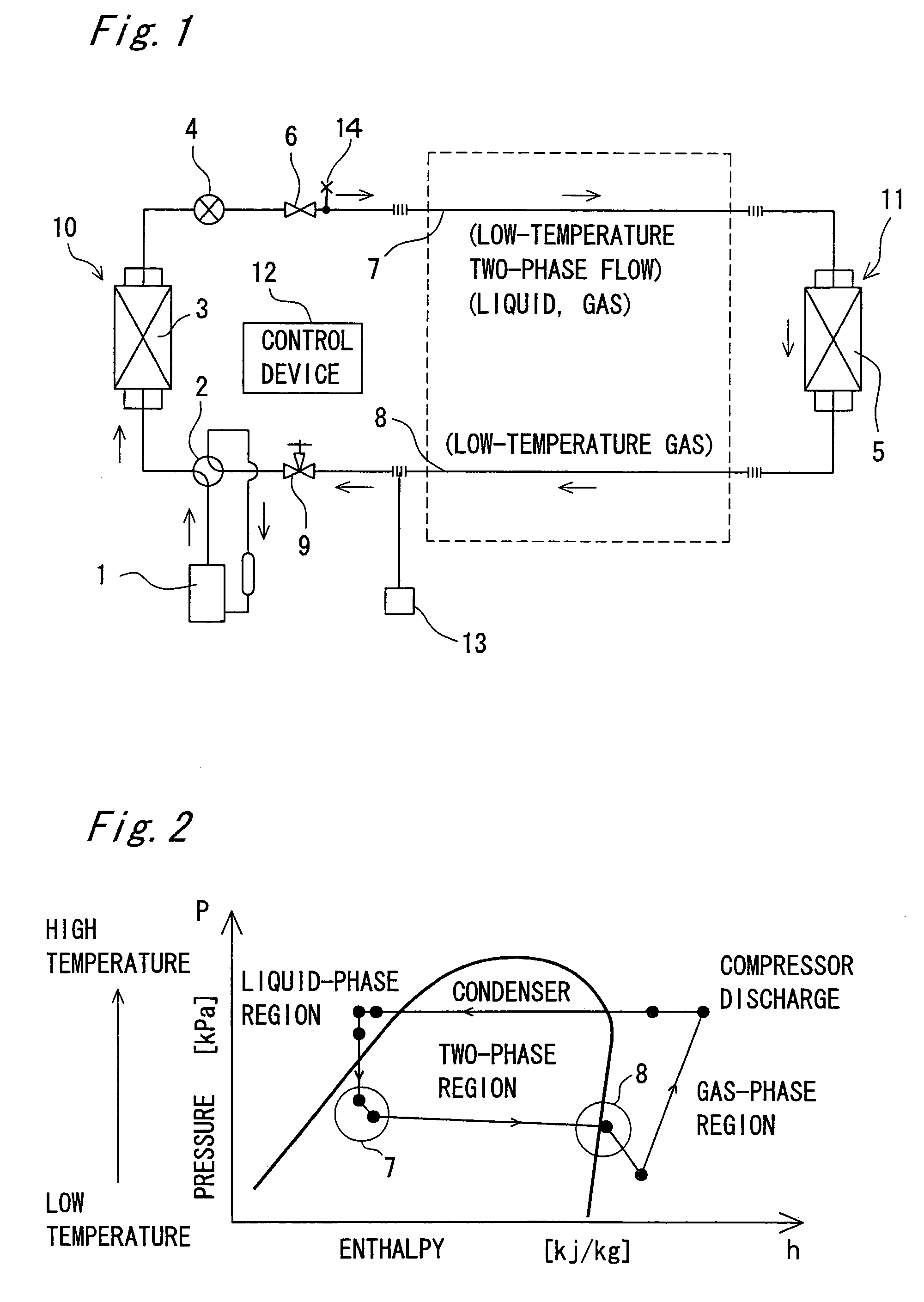
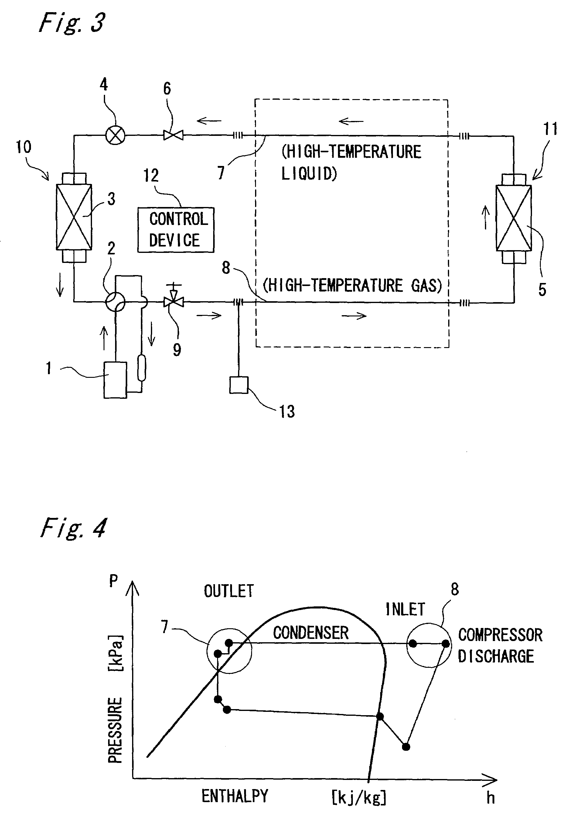
[0039]Description will be first made on the assumption that the air conditioner shown in FIG. 1 and FIG. 3 is the existing one. When carrying out the refrigerant and oil collection operation of the existing air conditioner, the four-way changeover valve 2 is first switched to the heating operation mode, and the heating operation (piping heating operation) is carried out. As shown in FIG. 6, this heating operation is carried out for about 10 minutes to 20 minutes. When the heating operation is started, the temperatures of the indoor heat exchanger (use side heat exchanger) 5, which functions as a condenser, and the interconnecting pipes 7 and 8 around it gradually rise. Then, a state in which the temperature of the indoor heat exchanger 5 becomes equal to or higher than 30° C. is secured for ten or more minutes, and the heating operation is ended. As described above, the state in which the temperature of the indoor heat exchanger 5 becomes equal to or higher than 30...

second embodiment

(Second Embodiment)

[0045]The refrigerant and oil collection operating method of the second embodiment will be described next. This is to carry out the refrigerant and oil collection operation for collecting the refrigerant still in the heating operation mode instead of collecting the refrigerant in the cooling operation mode after the end of the heating operation (piping heating operation) in the aforementioned first embodiment. In this case, the liquid shutoff valve 6 is provided with a service port 14 and the liquid refrigerant condensed by the indoor heat exchanger 5 is collected from this service port into a collecting vessel or the like. Moreover, it is acceptable to collect the refrigerant not from the service port but into the indoor heat exchanger 5 that is functioning as a condenser. With regard to the conditions of temperature, time and so on concerning the heating operation, the time to the start of the refrigerant and oil collection operation and so on are similar to tho...


PUM


Abstract

A method for refrigerant and oil collecting operation capable of assuring the cleanliness of the inside of an existing communication pipe at a low cost and installing, at a low cost, a new air conditioner, comprising a compressor (1), a heat source side heat exchanger (3), a decompressing mechanism (4), and a user side heat exchanger (5), comprising the steps of performing a pipe heating operation in a heating operation mode and performing a refrigerant and oil collecting operation to collect refrigerant to a heat source side heat exchanger (3), namely, with the refrigerant heated to a temperature higher than that where contaminants such as refrigerator oil inside a refrigerant circuit is dissolved into the refrigerant, performing the refrigerant and oil collecting operation so as to assure the cleanliness of the inside of the existing communication pipes (7, 8).

Description

[0001]This application is the national phase under 35 U.S.C. § 371 of PCT International Application No. PCT / JP01 / 03550 which has an International filing date of Apr. 25, 2001, which designated the United States of America.TECHNICAL FIELD[0002]This invention relates to a refrigerant and oil collection operating method, and in particular, to a refrigerant and oil collection operating method and refrigerant and oil collection control device, which can restrain the occurrence of various troubles when the existing interconnecting piping is reused by effectively collecting the contaminants of a residual refrigerating machine oil, oils other than the refrigerating machine oil, moisture, air, wear metal powders, dust and so on in the existing interconnecting piping together with the refrigerant.BACKGROUND ART[0003]Since the Freon-based refrigerants have been subject to the chlorofluorocarbon control, an HFC-based refrigerant has become used as an alternative refrigerant. This HFC-based refr...

Claims


Application Information

Patent Timeline
Patent Type & Authority Patents(United States)
IPC IPC(8): F25B43/02F25B43/00F25B43/04F25B47/00F25B13/00F25B45/00
CPCF25B13/00F25B45/00F25B43/02F25B2400/19F25B2400/18
Inventor TAIRA, SHIGEHARUTANAKA, JUNICHIROU
Owner DAIKIN IND LTD
Why Eureka
Try Eureka