Image forming apparatus

a technology of image forming apparatus and forming tube, which is applied in the direction of electrographic process, instruments, transportation and packaging, etc., can solve the problem of information leakage that cannot be prevented, and achieve the effect of preventing information leakag

Active Publication Date: 2010-01-07
SHARP KK
View PDF4 Cites 4 Cited by
  • Summary
  • Abstract
  • Description
  • Claims
  • Application Information

AI Technical Summary

Benefits of technology

[0009]The present invention has been devised in view of the above conventional problem, it is therefore an object of the present invention to provide an image forming apparatus which can prevent information leakage by making it difficult to look particular information that is recorded on the output paper from the image forming apparatus.
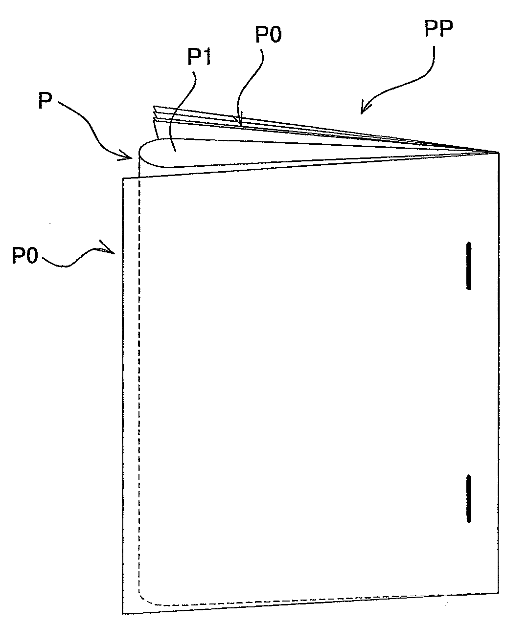
[0017]According to the first and second aspects of the present invention, since the image for pouch-binding that has been created by editing the layout of the confidential image is formed on the recording paper, it is possible to hide or obscure the confidential image, hence prevent leakage of confidential information, either in the state where the recording sheet is stapled or in the state where the sheet is left unstapled.
[0018]According to the third aspect of the present invention, it is possible to disclose confidential image information easily when needed.
[0019]According to the fourth aspect of the present invention, it is possible to arrange image information in the optimal position without having confidential image information bound up and hidden.
[0020]According to the fifth aspect of the present invention, it is possible to prevent part of confidential image information from being bound up and hidden.

Problems solved by technology

As a result, the above configuration still entails the problem that information leakage cannot be prevented.

Method used


Image

  • Image forming apparatus
  • Image forming apparatus
  • Image forming apparatus

Examples


Embodiment Construction

[0038]The embodiment of the present invention will hereinafter be described in detail with reference to the accompanying drawings.

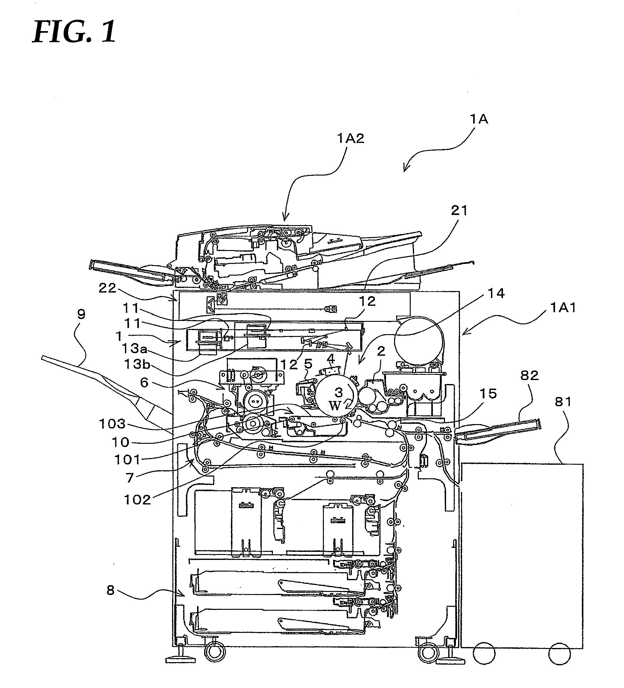
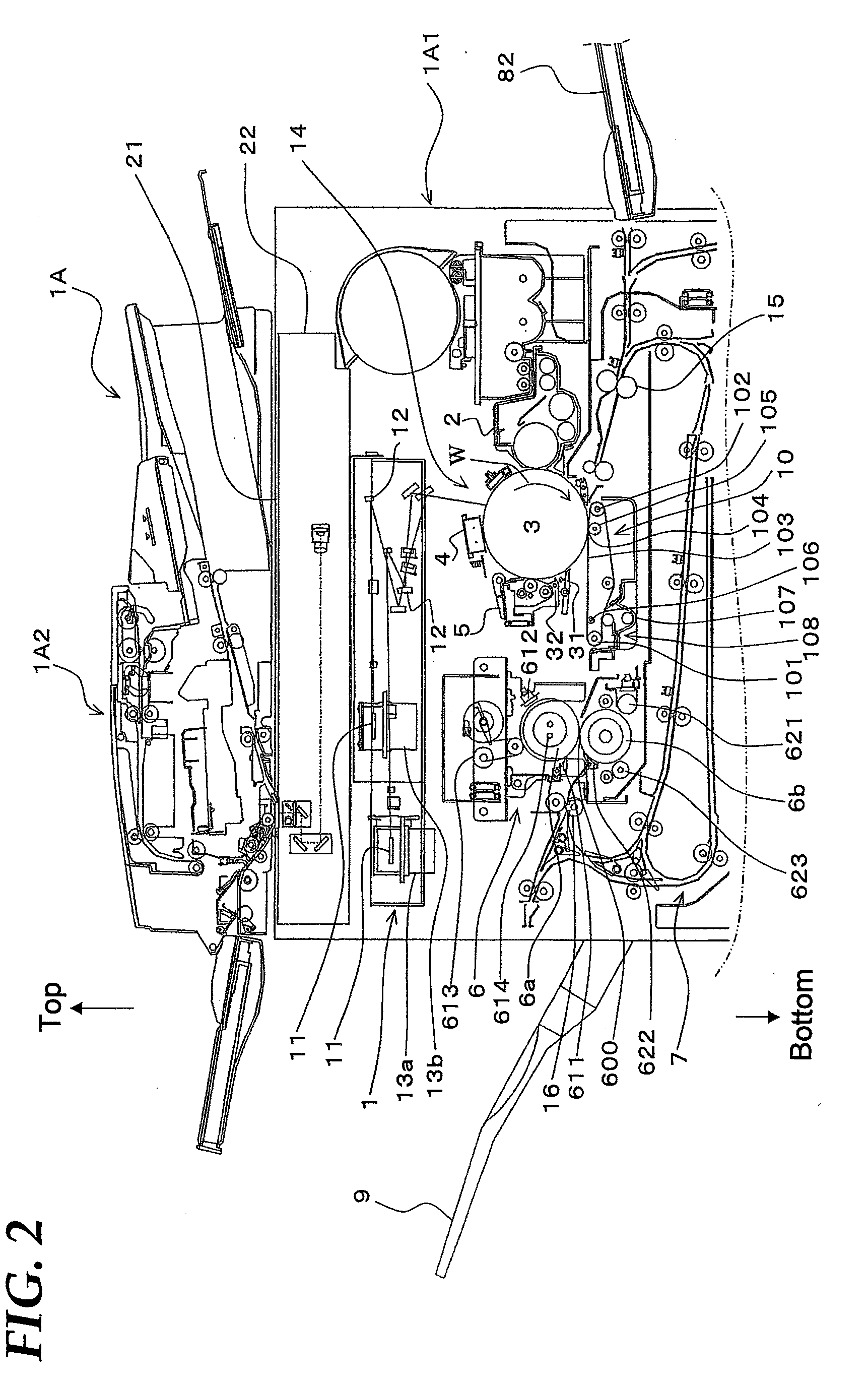
[0039]FIG. 1 is an illustrative view showing the overall configuration of an image forming apparatus according to the embodiment of the present invention. FIG. 2 is a partially detailed view showing the configuration of the apparatus body of the same image forming apparatus.

[0040]To begin with, the overall configuration of an image forming apparatus 1A according to the present embodiment will be described with reference to the drawings.

[0041]Image forming apparatus 1A according to the present embodiment electrophotographically forms and outputs monochrome images of image data that was transferred from the outside, on predetermined sheet-like recording paper (to be referred to hereinbelow as paper) as recording media.

[0042]Image forming apparatus 1A is composed of, as shown in FIGS. 1 and 2, an apparatus body 1A1 and an automatic document processor 1A2.

[00...


PUM

PropertyMeasurementUnit
resistivityaaaaaaaaaa
electricaaaaaaaaaa
transparentaaaaaaaaaa

Abstract

The image forming apparatus includes: an image processor; an image forming portion for forming images on recording paper based on the image data output from the image processor; a folding mechanism for folding the recording paper with images formed by the image forming portion when the input image information is confidential image information; and a stapling mechanism for binding the recording paper folded by the folding mechanism, at the end part when the input image information is confidential image information. When the input image information is confidential image information, the image forming portion outputs the pouch-binding image data for a pouch-bound image to be formed on the facing pages of the recording paper that is folded by the folding mechanism, by editing the layout of the confidential image.

Description

[0001]This Nonprovisional application claims priority under 35 U.S.C. §119(a) on Patent Application No. 2008-174593 filed in Japan on 3 Jul. 2008, the entire contents of which are hereby incorporated by reference.BACKGROUND OF THE INVENTION[0002](1) Field of the Invention[0003]The present invention relates to an image forming apparatus, in particular, relating to an image forming apparatus that is controlled to perform image output based on electrophotography.[0004](2) Description of the Prior Art[0005]Recently, image forming apparatuses such as copiers, facsimile machines and the like, are configured to be able to easily perform image output by remote control from external devices such as PC terminals and the like. The documents output from the image forming apparatus can be usually stacked on the paper output tray and collected in a simple manner.[0006]However, the documents on this paper output tray are exposed to the state in which any one can easily pick them up or any one can ...

Claims


Application Information

Patent Timeline
Patent Type & Authority Applications(United States)
IPC IPC(8): B65H45/10
CPCG03G15/6541G03G2215/00932G03G2215/00877G03G2215/00827
Inventor NISHIMURA, MICHIAKI
Owner SHARP KK
Why Eureka
Try Eureka