Method and Apparatus for Synchronizing Time Stamps

a time stamp and time stamp technology, applied in the field of time stamp synchronization methods and apparatuses, can solve the problems of complex generation of precise time stamps for high speed events, and it is impossible for conventional electronic time stamp circuits to run and count quickly enough to provide the required resolution

Active Publication Date: 2010-01-07
TEXAS INSTR INC
View PDF4 Cites 13 Cited by
  • Summary
  • Abstract
  • Description
  • Claims
  • Application Information

AI Technical Summary

Benefits of technology

[0007]Other embodiments of the present invention provide methods for synchronizing time stamps. One particular embodiment of a method for synchronizing time stamps includes determining whether an event signal transitions during a first phase or a second phase of a clock signal, determining whether a fine time stamp value from a fine time stamp generator is greater than at least one threshold value, and, based at least in part on a clock phase during which the event signal transitions and a determination of whether the fine time stamp value is greater than the at least one threshold value, selecting one of a plurality of coarse time stamp values to combine with the fine time stamp value. In some particular embodiments, a greater coarse time stamp value is selected when the fine time stamp value is less than the at least one threshold value and a smaller coarse time stamp value is selected when the fine time stamp value is greater than the at least one threshold value.
[0008]Another particular embodiment of an apparatus for synchronizing time stamps includes an event signal input, a clock input, a coarse time stamp generator, a fine time stamp generator and a synchronizer. The coarse time stamp generator has an input connected to the clock input, and has a counter having an input connected to the clock input and a bank of latches connected to an output of the counter. The fine time stamp generator has a first input connected to the clock input, a second input connected to the event signal input, and a synchronization signal output. The fine time stamp generator is an interpolator having a flash based architecture that captures a value for a fine time stamp indicating a relative time between edges of a clock signal on the clock input at which the event signal transitioned. The fine time stamp generator also includes a bank of latches. The synchronizer includes a clock phase detector and a clock edge selector. The clock phase detector has a first input connected to the clock input, a second input connected to the event signal input and a clock phase indicator output. The clock phase detector is adapted to

Problems solved by technology

Generating precise time stamps for high speed events thus becomes complicated by the difficulty in generating high speed clocks and electronic circuits that can count the high speed clocks.
Thus

Method used


Image

  • Method and Apparatus for Synchronizing Time Stamps
  • Method and Apparatus for Synchronizing Time Stamps
  • Method and Apparatus for Synchronizing Time Stamps

Examples


Embodiment Construction

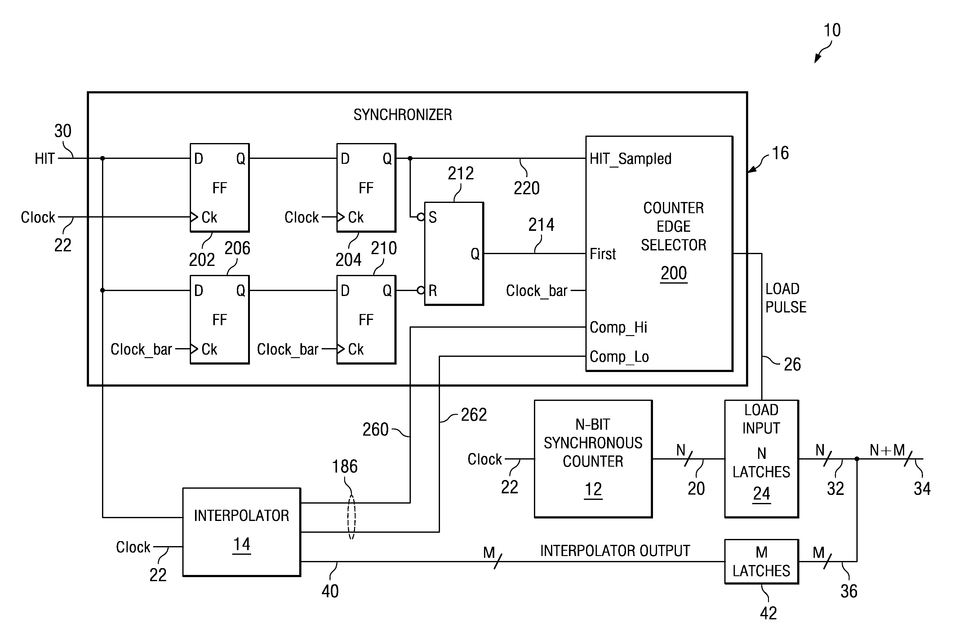
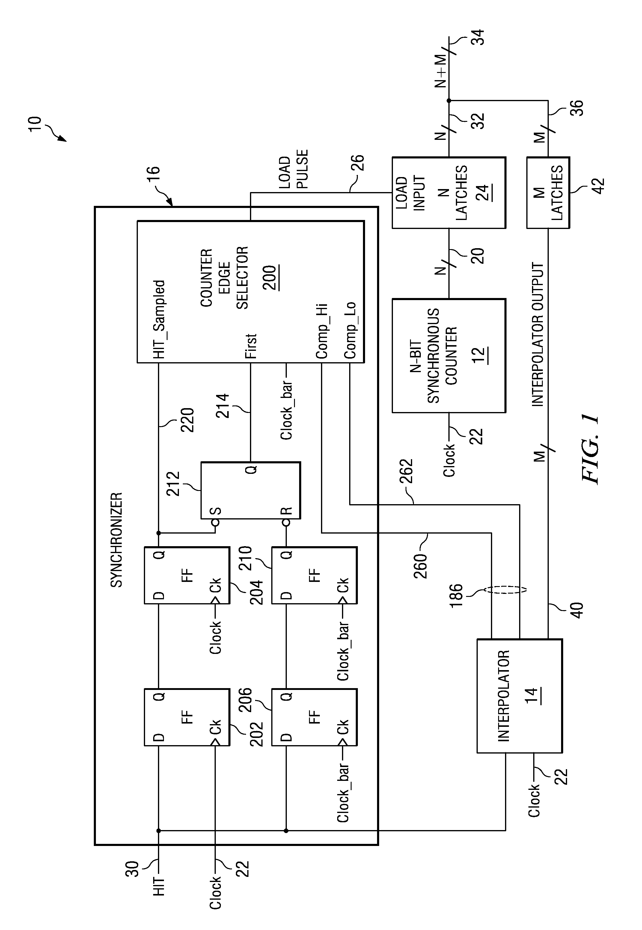
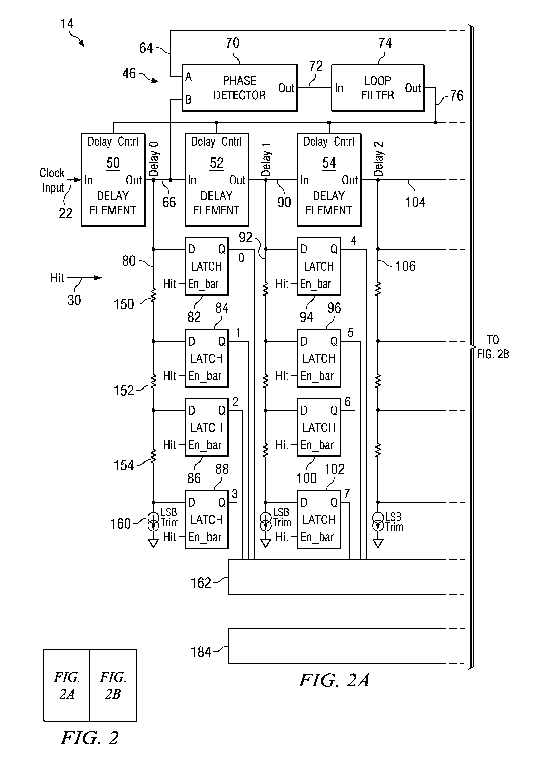
[0019]The present invention is related to time stamp apparatuses, and in particular to interpolating time stamp apparatuses with a flash-based architecture. The time stamp apparatuses generate a time stamp when an event occurs by capturing the state of an electronic counter when an event signal changes state. The time stamp apparatuses disclosed herein generate a time stamp using a combination of a coarse time sample and a fine time sample. The counter generates the coarse time sample and an interpolator generates the fine time sample, improving the counter time stamping resolution by a factor of 2M, for example by 64 in one particular embodiment, by interpolating between counter clock edges. The interpolator has a flash-based architecture that simultaneously samples the state of the event signal at multiple fractions of the counter clock period. The flash architecture provides for very high data throughput and very high precision, without the need for trimming. One particular embod...


PUM


Abstract

Various apparatuses and methods for synchronizing time stamps are disclosed herein. For example, some embodiments of the present invention provide apparatuses for synchronizing a coarse time stamp with a fine time stamp. Such apparatuses include an event signal input, a clock input, a coarse time stamp generator having an input connected to the clock input, and a fine time stamp generator having a first input connected to the clock input, a second input connected to the event signal input, and a synchronization signal output. The apparatuses also include a synchronizer having a first input connected to the clock input, a second input connected to the event signal input, a third input connected to the synchronization signal output and an output connected to the coarse time stamp generator. The synchronizer is adapted to synchronize the coarse time stamp generator to the fine time stamp generator based at least in part on the synchronization signal output. The apparatuses are adapted to combine a synchronized coarse time stamp from the coarse time stamp generator with a fine time stamp from the fine time stamp generator to form a time stamp indicating when an event signal transitioned on the event signal input.

Description

CROSS REFERENCE TO RELATED APPLICATION[0001]The present application claims priority to (i.e., is a non-provisional of) U.S. Provisional Patent Application No. 61 / 077,870 entitled “Method and Apparatus for Synchronizing Time Stamps”, and filed Jul. 3, 2008 by Brantley et al. The aforementioned application is assigned to an entity common hereto, and the entirety of the aforementioned application is incorporated herein by reference for all purposes.BACKGROUND OF THE INVENTION[0002]Electronic time stamp or time measurement circuits are used to produce highly precise digital time measurements for a wide variety of applications such as automated test equipment, bench top time measurement equipment, radar and sonar devices, etc. Conventional time stamp circuits generate the time stamps using a digital counter that increments at each rising edge of an oscillating clock signal, with the resulting count from the digital counter representing the time at which an event occurred. For example, th...

Claims


Application Information

Patent Timeline
IPC IPC(8): H03L7/00
CPCG04F10/04H03L7/10H03L7/0812G04F10/06H03L7/0816H03L7/0818
Inventor BRANTLEY, STEVEN GRAHAMMACLEAN, JAMES RICHARDCAVALIERE, FRANCESCO
Owner TEXAS INSTR INC
Why Eureka
Try Eureka