Image display apparatus, integrated circuit, and computer program

a display apparatus and integrated circuit technology, applied in the field of plasma display, can solve the problems of flicker not being adequately suppressed, the display quality deteriorates, and the sight line movement direction cannot be correctly detected, so as to suppress image blur, suppress image blur, suppress image blur

Inactive Publication Date: 2010-01-07
PANASONIC CORP
View PDF5 Cites 8 Cited by
  • Summary
  • Abstract
  • Description
  • Claims
  • Application Information

AI Technical Summary

Benefits of technology

[0055]That is, an image display apparatus which controls subfields by estimating a motion vector, and determines, via a reliability calculation unit, reliability of a motion vector calculated by a motion vector calculation unit, and, via a subfield display control unit, disperses light emission of subfields having high luminance in a direction of the motion vector when the reliability is high, and concentrates the light emission in the direction of the motion vector when the reliability is low, thereby suppressing image blur, flicker, and so on. In other words, an image display apparatus may be adopted which suppresses image blur, flicker, and so on in a plasma display that controls light emission through subfield control based on a motion vector and reliability thereof.
[0056]The present invention makes it possible to suppress occurrence of image blur and pseudo-contours in video in plasma displays that perform light-emission control by controlling subfields.

Problems solved by technology

The sight-line movement direction, however, cannot be detected correctly in some cases.
However, when the sight-line movement direction is not correctly detected, that is, for example, when a direction 180 degrees different from the actual sight-line movement direction is detected, there is a problem that the display quality rather deteriorates because the subfields are displayed along the direction 180 degrees different from the actual sight-line movement direction.
Therefore, when the technique of Patent Reference 2 is adopted in displaying moving picture-based video, flicker cannot be adequately suppressed because although the sight line moves, the subfields having larger luminance weights at the position before the sight-line movement emit light, resulting in image blur and so on.
Further, there is also a problem that incorrect detection of moving pictures and still pictures causes deterioration in the display quality.

Method used


Image

  • Image display apparatus, integrated circuit, and computer program
  • Image display apparatus, integrated circuit, and computer program
  • Image display apparatus, integrated circuit, and computer program

Examples


Embodiment Construction

)

[0072]With reference to the drawings, an embodiment of an image processing apparatus (image display apparatus) according to the present invention shall be hereinafter described.

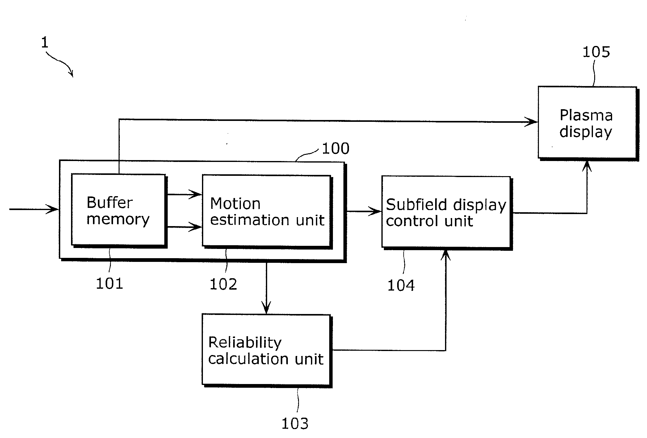
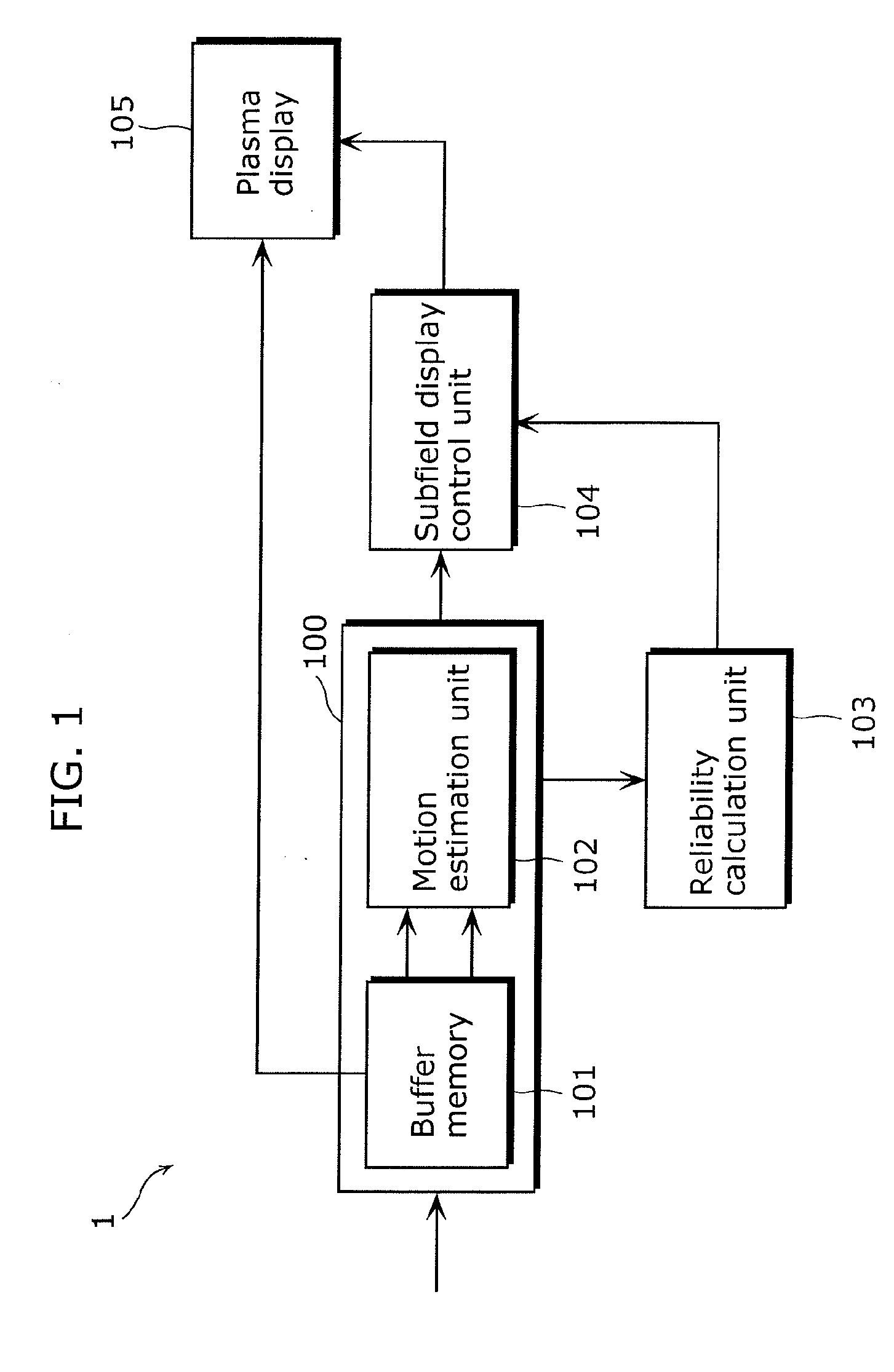
[0073]FIG. 1 is a block diagram of a video display apparatus 1 according to the present embodiment.

[0074]The video display apparatus 1 includes: an image processing unit 100 which contains a buffer memory 101 and a motion estimation unit 102; a reliability calculation unit 103; a subfield display control unit 104; and a plasma display 105.

[0075]It should be noted that the image processing unit 100, the reliability calculation unit 103, and the subfield display control unit 104 are, for example, functional blocks realized on a substrate of a driving chip provided in the plasma display 105 for driving the plasma display 105. Here, the driving chip is provided in the plasma display 105, for example.

[0076]Pictures to be displayed by the plasma display 105 are temporarily accumulated in the buffer memory 101 of t...


PUM


Abstract

Achieved are suppression of image-quality deterioration caused by an incorrect motion vector and suppression of flicker in video without causing adverse effects such as image blur. A video display apparatus performs multi-level gradation display by controlling light emission of subfields into which one field displaying a picture is divided, the video display apparatus comprising: an image processing unit configured to calculate a motion vector of the picture; a reliability value calculation unit configured to calculate a reliability value of the calculated motion vector; and a subfield display control unit configured to determine a subfield control pattern based on the calculated reliability value, and to control the light emission according to the determined subfield control pattern.

Description

BACKGROUND OF THE INVENTION[0001](1) Field of the Invention[0002]The present invention relates to a plasma display, and particularly to a video display method and a video display apparatus for performing display control to suppress flicker and deterioration in video resolution.[0003](2) Description of the Related Art[0004]Half-tone display by plasma displays (hereinafter referred to as PDPs) is achieved by displaying subfields having different luminance weights into which one field is divided. It is known that when images with motions are displayed by dividing one field into plural subfields by time division, image blur and pseudo-contours in video occur due to a mismatch between the sight-line movement direction and half-tone display positions.[0005]As a method to reduce such occurrence, Patent Reference 1 (Japanese Unexamined Patent Application Publication No. 9-138666) discloses correcting display positions of subfields in the moving direction of video and displaying the video ac...

Claims


Application Information

Patent Timeline
Patent Type & Authority Applications(United States)
IPC IPC(8): G06K9/48G06T1/00H04N5/66G09G3/20G09G3/28
CPCG09G3/2022G09G2320/106G09G2320/0266G09G3/2803
Inventor NAGAISHI, YUJITAKEDA, HIDETOSHIKOBAYASHI, TAKAHIRO
Owner PANASONIC CORP
Why Eureka
Try Eureka