Illuminating device and annular heat-dissipating structure thereof

a technology of illumination device and heat dissipation structure, which is applied in semiconductor devices, light sources, light-emitting devices, etc., can solve the problems of high wattage devices, insufficient heat dissipation of heat generated, and insufficient thickness of thermal conducting plates, etc., to achieve the effect of increasing the number of thermal conducting plates and reducing material costs

Inactive Publication Date: 2010-01-07
DELTA ELECTRONICS INC
View PDF4 Cites 80 Cited by
  • Summary
  • Abstract
  • Description
  • Claims
  • Application Information

AI Technical Summary

Benefits of technology

[0007]In view of the foregoing, the present invention is to provide an illuminating device and an annular heat-dissipating structure thereof that can decrease the material cost and increase the number of the thermal conducting plates and the heat-dissipating surface.

Problems solved by technology

This structure is applied to most of the present illuminating devices, but the heat sink 14 may be not enough for dissipating the heat generated by the illuminating device with high watts.
In addition, since the heat sink is made by aluminum extrusion or casting, the thickness of the thermal conducting plate 13 can not be reduced due to the limitation of manufacturing process.
Thus, in the limited space, the number of the thermal conducting plates 13 is also limited, so that the total heat-dissipating surface can not be increased.
Moreover, the conventional structure utilizes the thermal conducting plate to connect the aluminum substrate and the heat sink, so that the additional material cost is necessary.

Method used


Image

  • Illuminating device and annular heat-dissipating structure thereof
  • Illuminating device and annular heat-dissipating structure thereof
  • Illuminating device and annular heat-dissipating structure thereof

Examples


Embodiment Construction

[0024]The present invention will be apparent from the following detailed description, which proceeds with reference to the accompanying drawings, wherein the same references relate to the same elements.

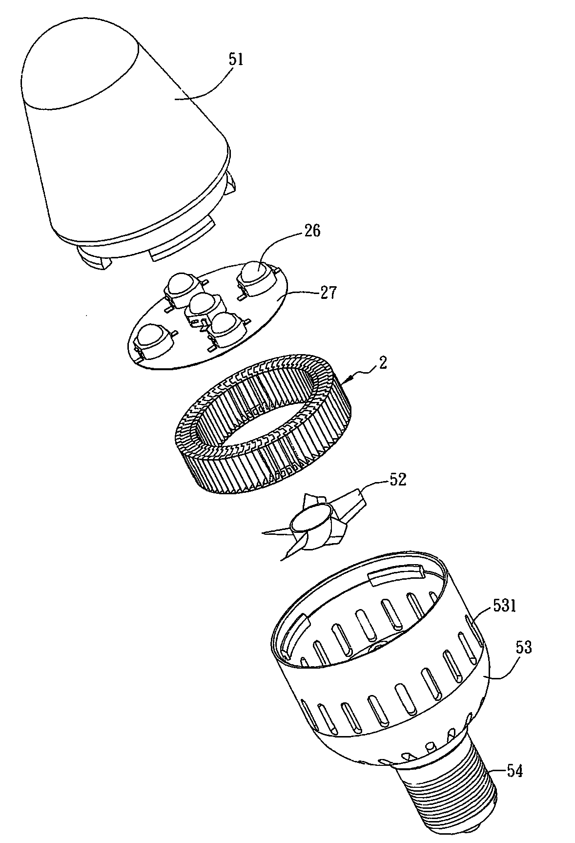
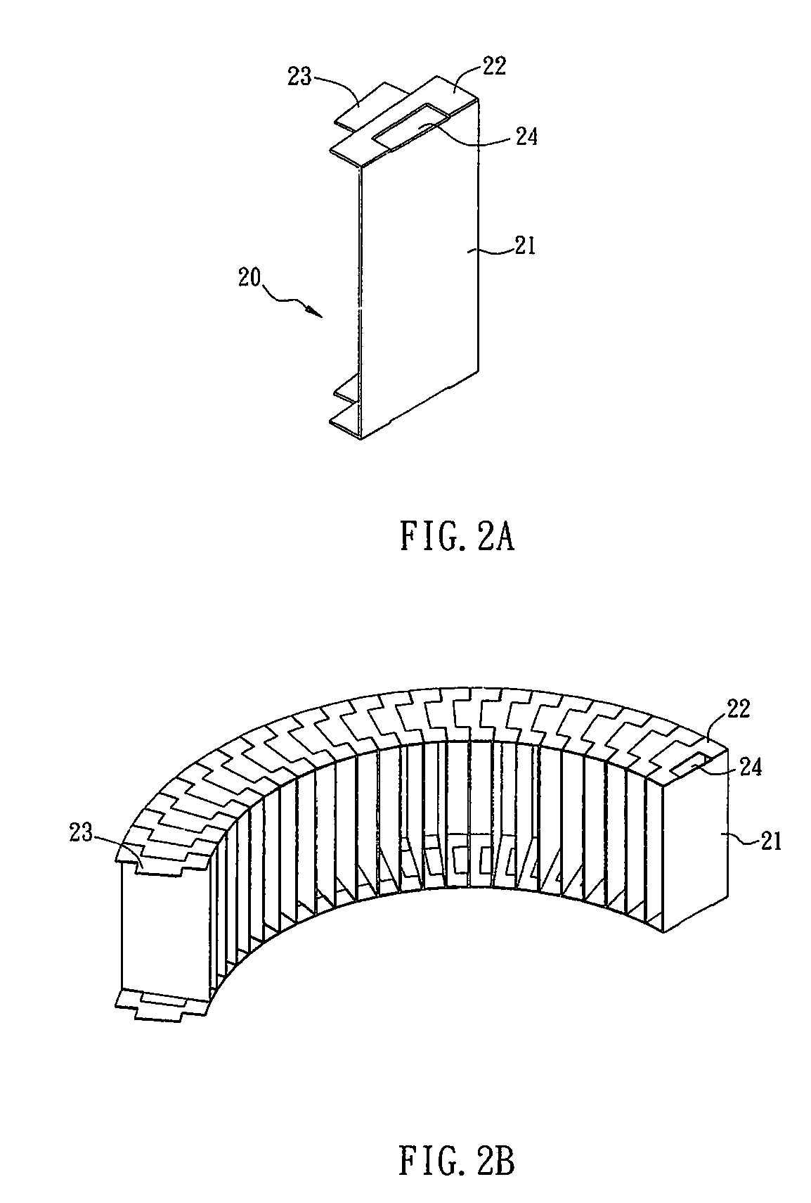
[0025]FIGS. 2A to 2D are schematic diagrams showing an annular heat-dissipating structure 2 according to a first embodiment of the present invention. With reference to FIGS. 2A to 2D, the annular heat-dissipating structure 2 has an airflow passage 25 disposed at the center thereof. As shown in FIG. 2C, the annular heat-dissipating structure 2 includes a plurality of heat-dissipating units 20 disposed around the airflow passage 25. Each heat-dissipating unit 20 includes a flake 21, a bending portion 22, a first assembling portion 23 and a second assembling portion 24. As shown in FIG. 2A, the bending portion 22 can be formed by bending two ends of the flake 21, and the width of one end of the bending portion 22 is smaller than that of the other end of the bending portion 22. Thus, the ...


PUM


Abstract

An illuminating device and an annular heat-dissipating structure thereof. The annular heat-dissipating structure includes a plurality of heat-dissipating units disposed circumambiently. Each heat-dissipating unit includes a flake and at least one first assembling portion connected with the flake, so that the adjacent heat-dissipating units can be connected with each other.

Description

CROSS REFERENCE TO RELATED APPLICATIONS[0001]This Non-provisional application claims priority under 35 U.S.C. §119(a) on Patent Application No(s). 097125157 filed in Taiwan, Republic of China on Jul. 4, 2008, the entire contents of which are hereby incorporated by reference.BACKGROUND OF THE INVENTION[0002]1. Field of Invention[0003]The present invention relates to an illuminating device and an annular heat-dissipating structure thereof. More particularly, the present invention relates to a heat-dissipating structure composed of a plurality of heat-dissipating units, which are disposed circumambiently.[0004]2. Related Art[0005]In the present marketing, the light-emitting diodes (LED) have been used as the light source of various illuminating devices, such as the street lamp, wall lamp, desk lamp, light bulb and light tube. Taking the light bulb or tube for example, the LED illuminating device, which is used in office or house, is usually manufactured to fit the common socket, such a...

Claims


Application Information

Patent Timeline
Patent Type & Authority Applications(United States)
IPC IPC(8): F21V29/02
CPCF21V3/00F21V29/02F21Y2101/02F21K9/13F21V29/83F21V29/677F21V29/773F21V29/80F21K9/135F21V29/70F21K9/23F21K9/232F21Y2115/10
Inventor WU, HSIANG-CHENCHENG, CHIN-MINGYU, CHIH-HAOCHIU, TE-HSINHSU, HAN-CHUNG
Owner DELTA ELECTRONICS INC
Why Eureka
Try Eureka