Light guide bar with patterned surface to enhance light uniformity and intensity

Inactive Publication Date: 2010-01-07
PIXON TECH CORP
View PDF7 Cites 26 Cited by
  • Summary
  • Abstract
  • Description
  • Claims
  • Application Information

AI Technical Summary

Benefits of technology

[0009]To achieve these and other advantages and in order to overcome the disadvantages of the conventional method in accordance with the purpose of the invention a

Problems solved by technology

However, since the end of the transparent light rod 120 is flat, much of the light is reflected back and is lost.
This lowers the efficiency and intensity of the light source.
Unfortunately, some of the light exits th

Method used


Image

  • Light guide bar with patterned surface to enhance light uniformity and intensity
  • Light guide bar with patterned surface to enhance light uniformity and intensity
  • Light guide bar with patterned surface to enhance light uniformity and intensity

Examples


Embodiment Construction

[0043]Reference will now be made in detail to the preferred embodiments of the present invention, examples of which are illustrated in the accompanying drawings. Wherever possible, the same reference numbers are used in the drawings and the description to refer to the same or like parts.

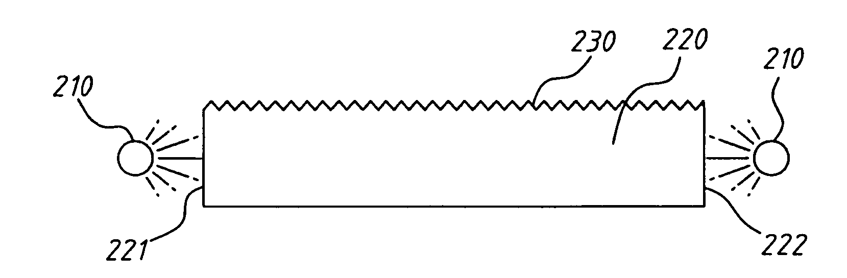
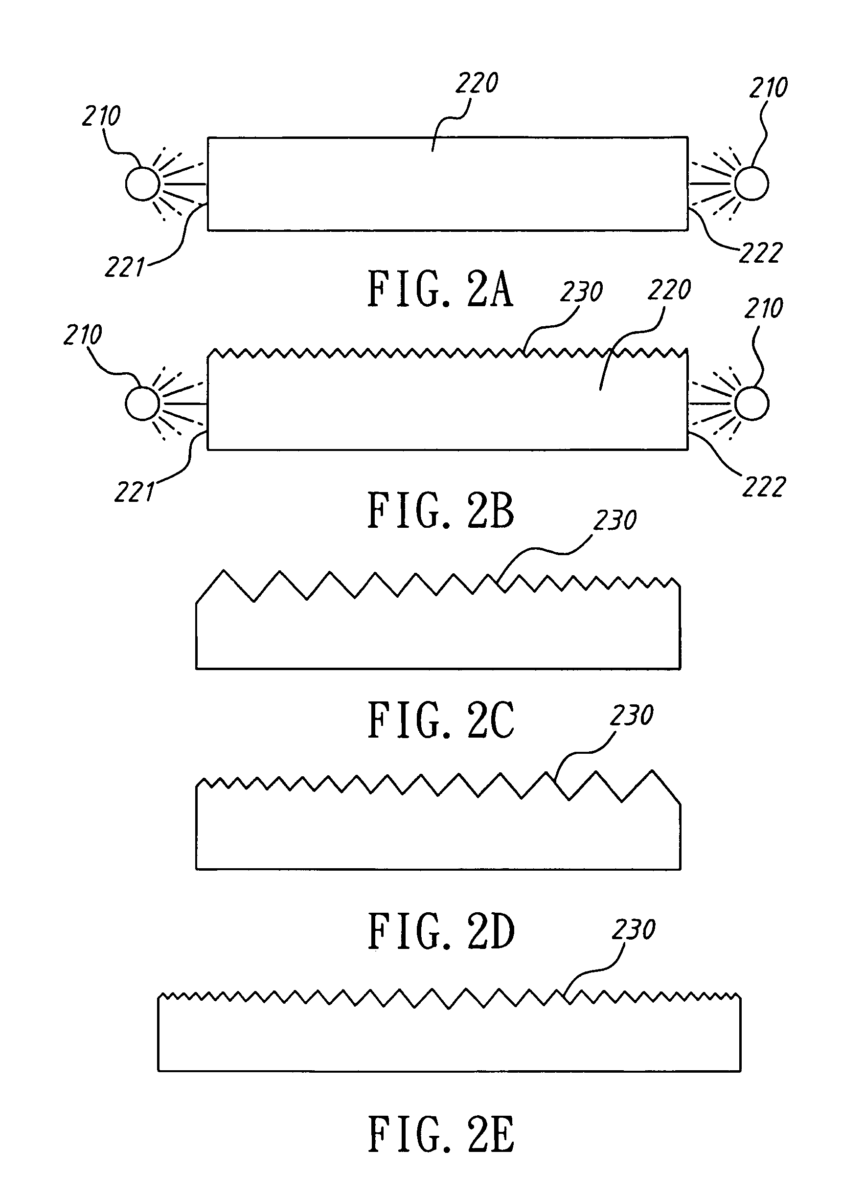
[0044]Refer to FIG. 2A, which is a drawing illustrating a flicker free light source with a light guide bar according to an embodiment of the present invention. The flicker free light source comprises a light emitting diode (LED) light source 210 disposed on each end of a light guide bar 220. The light guide bar 220 is comprised of transparent or semi-transparent material. The light guide bar is solid, hollow, or semi-hollow. The light guide bar 220 further comprises two ends 221222.

[0045]Refer to FIG. 2B, which is a drawing illustrating a flicker free light source with a light guide bar having a light diffusing patterned surface according to an embodiment of the present invention.

[0046]As shown in FI...


PUM


Abstract

A light guide bar with a patterned surface for a flicker free light source comprising a light emitting diode (LED) light source disposed on each end of the light guide bar is disclosed. A light diffusing pattern is disposed on a light emitting surface. The light diffusing pattern comprises a plurality of notches that are smallest closest to the LED light sources and largest in the center of the light guide bar. A light reflecting pattern is disposed on a light reflecting surface opposite the light diffusing pattern on the light emitting surface. Light emitted by the LED light sources enters the light guide bar through the ends. The light travels through the light guide bar at various angles and is reflected by the light reflecting pattern on the light reflecting surface. The reflected light is then emitted through the light diffusing pattern on the light emitting surface.

Description

BACKGROUND OF THE INVENTION[0001]1. Field of the Invention[0002]The present invention relates to a light source. More specifically, the present invention discloses a highly efficient light source that does not flicker and provides a uniform emitted light.[0003]2. Description of the Prior Art[0004]Linear light sources emit light in a different direction from the direction the light originated from. For example, a light is produced by a light emitting diode at an angle of zero degrees. By affecting the direction of the light beam the linear light source can emit the light at various angles such as 90 degrees.[0005]Refer to FIG. 1, which is a drawing illustrating a light source of the prior art. As shown in FIG. 1, the conventional light source comprises a light emitting diode 110 and a transparent light rod 120. Both ends of the transparent light rod 120 are flat surfaces. When power is applied to the light emitting diode 110 the light emitting diode 110 emits light. Some of the light...

Claims


Application Information

Patent Timeline
IPC IPC(8): G02B5/02
CPCG02B6/0038G02B6/001
Inventor WU, RONG-YAWYEN, CHIH MINGLIAO, CHIEN LIANGCHEN, YEN-CHIEH
Owner PIXON TECH CORP
Why Eureka
Try Eureka