Passive Cooling Systems for Network Cabinet

a passive cooling and network cabinet technology, applied in ventilation systems, heating types, electrical apparatus casings/cabinets/drawers, etc., can solve the problems of difficult installation of passive cooling systems in existing network cabinets, less expensive, and require more space than a comparable active cooling system, and achieves easy installation and easy sharing.

Active Publication Date: 2010-01-07
PANDUIT
View PDF65 Cites 84 Cited by
  • Summary
  • Abstract
  • Description
  • Claims
  • Application Information

AI Technical Summary

Benefits of technology

[0008]Therefore, there is a need for a passive cooling system that is modular and can be easily installed in existing network cabinets. There is also a need for a passive cooling system that can be easily shared by more than one network cabinet.

Problems solved by technology

Passive cooling systems are typically less expensive than active cooling systems, both to install and operate, but require more space than a comparable active cooling system.
However, installing passive cooling systems in existing network cabinets is particularly difficult because existing network cabinets have limited space.
One drawback to perforated doors if the exhaust flow is not controlled properly is that hot air exiting the cabinet may be recirculated into the surrounding environment, and eventually, back into the cabinet.
However, most network cabinets do not have enough space to accommodate a properly sized chimney and corresponding exhaust plenum, at least not one that can effectively cool the cabinet.
However, existing passive cooling systems are not designed to accommodate more than one cabinet.
Therefore, passive cooling systems are designed to accommodate a maximum heat load in each cabinet, rather than an average heat load across the entire data center, resulting in wasted resources.

Method used


Image

  • Passive Cooling Systems for Network Cabinet
  • Passive Cooling Systems for Network Cabinet
  • Passive Cooling Systems for Network Cabinet

Examples


Embodiment Construction

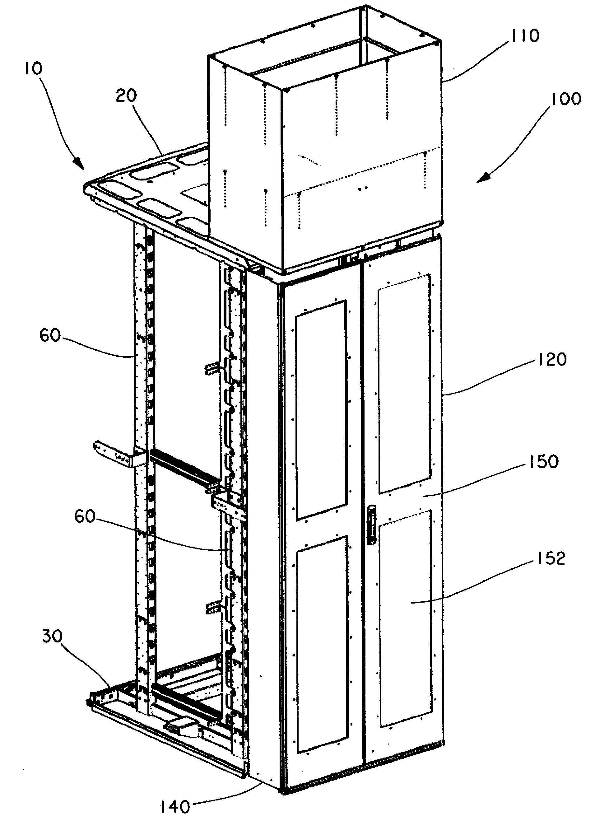
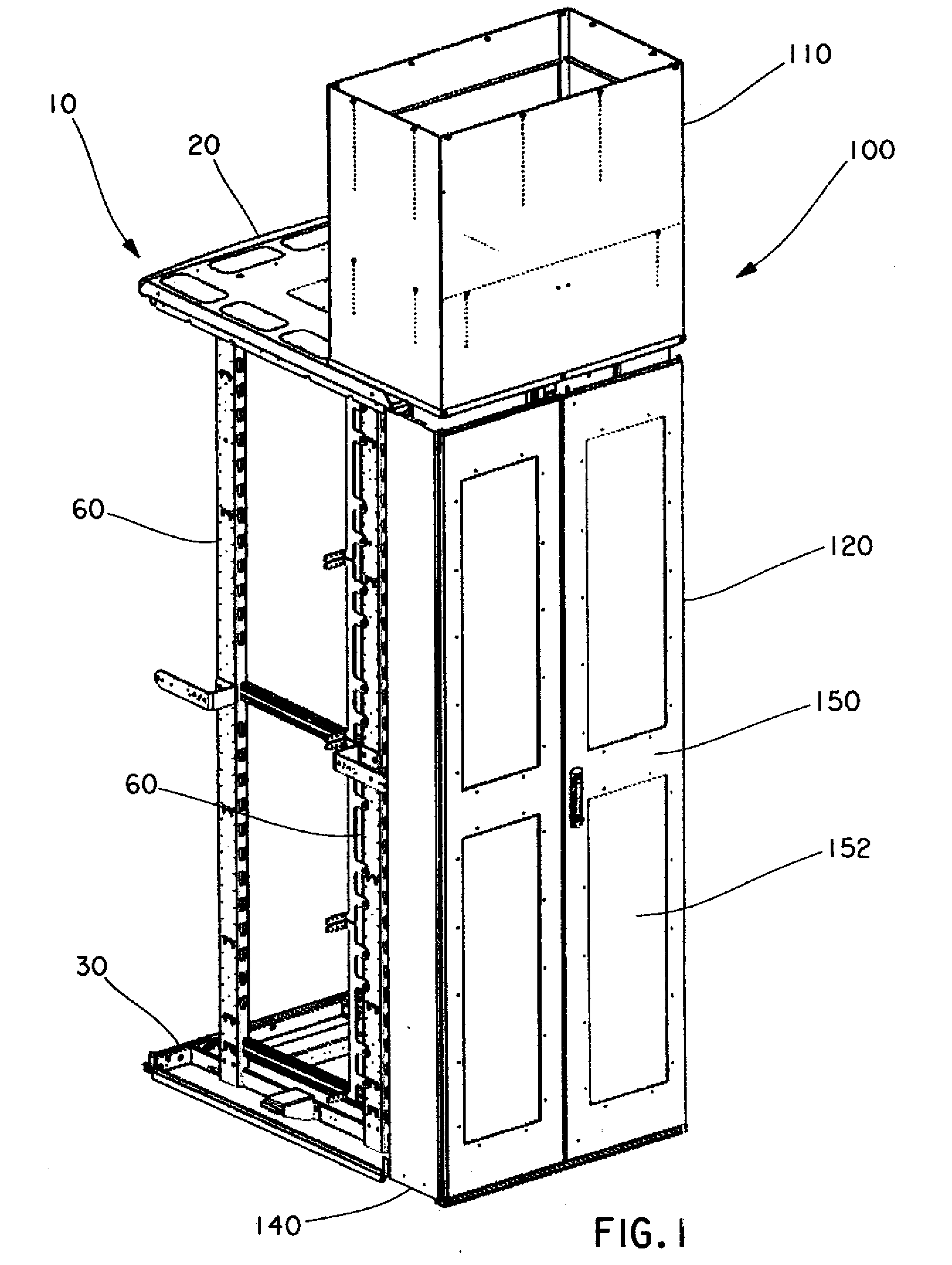
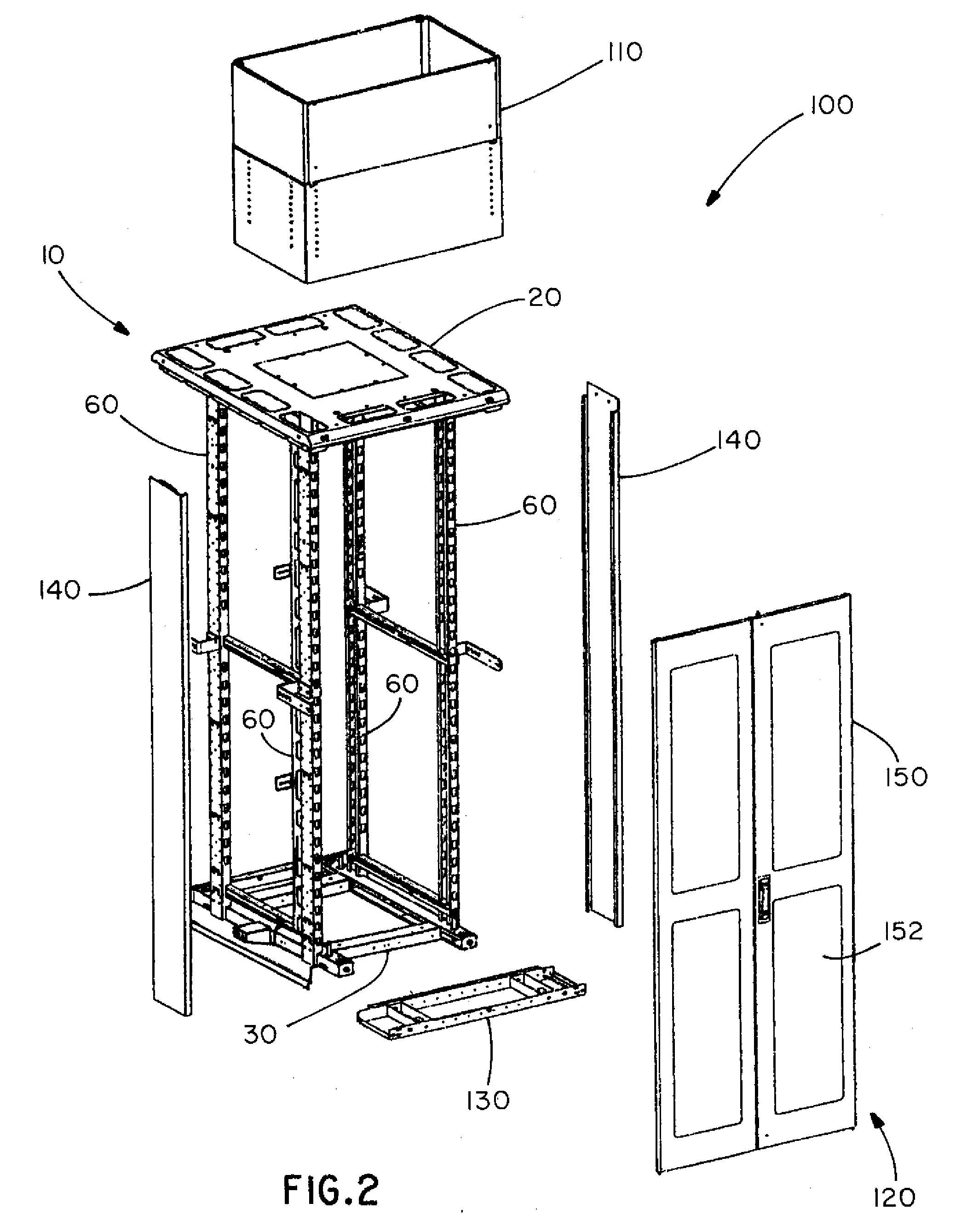
[0042]FIGS. 1-10 illustrate a passive cooling system 100 for a network cabinet 10, such as the PANDUIT® NET-ACCESS™ Cabinets, according to several embodiments of the present invention.

[0043]As best seen in FIG. 1, the passive cooling system 100 includes a chimney 110 and a cabinet extension 120. The chimney 110 is positioned above the cabinet extension 120, and overlaps a portion of the network cabinet 10.

[0044]As best seen in FIG. 2, the cabinet extension 120 includes a base 130, two side panels 140, and a back door 150. The cabinet extension 120 is positioned behind the network cabinet 10, and expands the volume of the network cabinet 10. The cabinet extension 120 and a portion of the network cabinet 10 that is adjacent to the cabinet extension 120 define an exhaust plenum 160 for the passive cooling system 100, as best seen in FIG. 7. Although the back door 150 is described with reference to the cabinet extension 120, it is understood that the back door 150 may be the back door 1...


PUM


Abstract

Certain embodiments of the present invention provide a cooling duct assembly for electronic equipment installed in a cabinet. The cooling duct assembly comprises at least one main duct in fluid communication with a front portion of the cabinet. The at least one main duct receives cold air from the front portion of the cabinet and routes the cold air toward a back portion of the cabinet. Additionally, the cooling duct assembly comprises at least one side duct in fluid communication with the at least one main duct. The at least one side duct receives the cold air from the at least one main duct and routes the cold air to at least one side air intake opening on the electronic equipment.

Description

CROSS REFERENCE TO RELATED APPLICATIONS[0001]This application claims priority to U.S. Provisional Patent Application No. 61 / 175,282, filed on May 4, 2009, and U.S. Provisional Patent Application No. 61 / 073,818, filed on Jun. 19, 2008, the subject matters of which are hereby incorporated by reference in their entireties.SUMMARY OF THE INVENTION[0002]Certain embodiments of the present invention provide a cooling duct assembly for electronic equipment installed in a cabinet. The cooling duct assembly comprises at least one main duct in fluid communication with a front portion of the cabinet. The at least one main duct receives cold air from the front portion of the cabinet and routes the cold air toward a back portion of the cabinet. Additionally, the cooling duct assembly comprises at least one side duct in fluid communication with the at least one main duct. The at least one side duct receives the cold air from the at least one main duct and routes the cold air to at least one side a...

Claims


Application Information

Patent Timeline
Patent Type & Authority Applications(United States)
IPC IPC(8): H05K5/00F24F7/00
CPCH05K7/20736
Inventor GRACZYK, FRANK J.RAMEY, SAMUEL C.FLEMING, JAMES N.HERBST, PAUL M.MCGRATH, MICHAEL J.WENTWORTH, JOSEPH D.EATON, ALVA B.
Owner PANDUIT
Why Eureka
Try Eureka