Method of Joint Inversion of Seismic Data Represented on Different Time Scales

a seismic data and time scale technology, applied in the field of geophysics, can solve the problems of difficult interpretation of data based on amplitude differences, difficult interpretation of characteristic differences of two seismic traces, and difficult definition of reliable velocity field with existing techniques

Active Publication Date: 2010-01-07
INST FR DU PETROLE
View PDF2 Cites 38 Cited by
  • Summary
  • Abstract
  • Description
  • Claims
  • Application Information

AI Technical Summary

Benefits of technology

[0032]defining a scale factor t1(t0) allowing synthetic data described in a first time scale t0 to be expressed in a second time scale t1, by a differential equation relating, by a function F, the traveltime variations of a seismic wave∂t1(t0)∂t0to the combinations of physical quantities, and by determining scale factor t1(t0) by solving the differential equation by a minimization method wherein the difference between∂t1(t0)∂t0and the function F is minimized; and

Problems solved by technology

The definition of a reliable velocity field with existing techniques however remains a very delicate operation (especially in heterogeneous media) and record section interpretation is in most cases achieved in the time domain.
In general, this technique is used when it is not possible to directly measure the parameters.
An important problem in the analysis of several data sets appears when these data sets are expressed in different time scales, which is the case with data obtained from repeated seismic surveys or multi-component seismic surveys.
Interpretation of data based on amplitude differences can however be sometimes difficult.
The characteristic differences of two seismic traces can therefore be difficult to interpret since they result from amplitude changes as well as time shifts that can hide these amplitude variations.
The drawback of these methods is that they are rather qualitative.
They allow detection of the zones that have undergone changes, but quantitative estimation of the intensity of these changes remains difficult.
In particular, this method hides the fact that this scale factor, depending on the ratio of the velocities of the P waves and the S waves, cannot have any value.
This can lead to physically impossible models.

Method used


Image

  • Method of Joint Inversion of Seismic Data Represented on Different Time Scales
  • Method of Joint Inversion of Seismic Data Represented on Different Time Scales
  • Method of Joint Inversion of Seismic Data Represented on Different Time Scales

Examples


Embodiment Construction

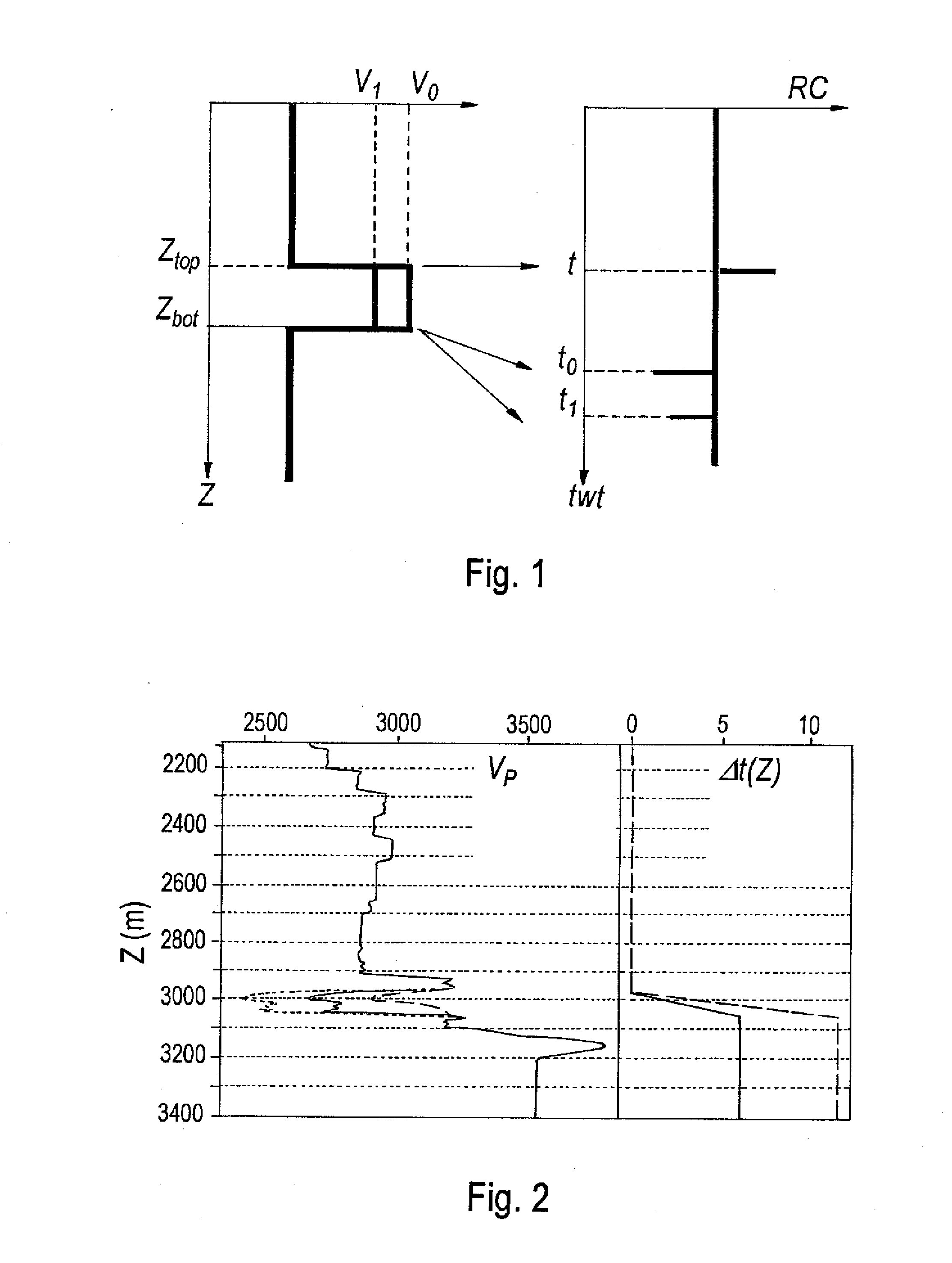
[0044]In rocks, velocity and density are physical parameters depending on the static (porosity, clay content, etc.) and dynamic (fluid content, pressure, temperature, relative permeability, etc.) properties thereof. It follows therefrom that, if these properties change in the subsoil over time, the elastic impedance contrasts in the medium can change, as well as the characteristics of the seismic signals (amplitudes, two-way traveltime of the waves, etc.) measurable at the surface.

[0045]Seismic measurements are thus conventionally used to obtain information on the characteristics of the subsoil formations: lithology, geometry, petrophysical properties, fluid saturations, pressure in the reservoir, etc. Although the vertical frequency resolution of these seismic data is lower than that of well data, they afford the advantage of providing larger-scale lateral information on the characteristics of the explored subsoil. Seismic surveys allow exploring large volumes of the subsoil and ha...


PUM


Abstract

A method of constructing an image representative of a heterogeneous medium by a procedure of joint inversion of seismic data represented on different time scales having an application for underground reservoir exploration. Sequential inversion of the seismic data is performed so as to determine a first model from the seismic data expressed in a first time scale, and a second model from the seismic data expressed in the second time scale. A scale factor t1(t0) allowing synthetic data described in a first time scale to be expressed in a second time scale is defined by a differential equation relating the traveltime variations of a seismic wave to the models resulting from the sequential inversion. Finally, joint inversion wherein a cost function using the scale factor is minimized is carried out so as to evaluate a difference between the synthetic data and the seismic data expressed in another time scale.

Description

BACKGROUND OF THE INVENTION[0001]1. Field of the Invention[0002]The invention relates to geophysics and notably to petroleum exploration using seismic methods.[0003]In particular, the invention relates to a seismic data stratigraphic inversion method for obtaining images representative of a heterogeneous medium such as the subsoil to, for example, allow characterization of hydrocarbon reservoirs.[0004]2. Description of the Prior Art[0005]Seismic exploration methods produce disturbances in the subsoil (emission of seismic waves in the subsoil by a seismic source) and in observing at the surface the waves reflected on the interfaces between the various geological layers of the earth, referred to as formations (such as sandstone, sand, shale layers), or refracted along some of these interfaces. Each time the seismic waves encounter a geological interface, part of these waves is reflected and travels up to the surface where it can be detected and recorded by a seismic wave pickups. Part...

Claims


Application Information

Patent Timeline
Patent Type & Authority Applications(United States)
IPC IPC(8): G01V1/28
CPCG01V11/00G01V1/30
Inventor TONELLOT, THIERRYBERNARD, MARIE-LISECLOCHARD, VINCENT
Owner INST FR DU PETROLE
Why Eureka
Try Eureka