
Direct fuel injection diesel engine

a technology of direct fuel injection and diesel engines, which is applied in the direction of combustion engines, cylinders, machines/engines, etc., can solve the problem of an increase in harmful exhaust substances

Inactive Publication Date: 2010-01-14
HONDA MOTOR CO LTD
View PDF3 Cites 31 Cited by
  • Summary
  • Abstract
  • Description
  • Claims
  • Application Information

AI Technical Summary

Benefits of technology

[0008]In accordance with the first aspect of the present invention, when the ratio of the entrance diameter D of the cavity recessed in the central part of the piston to the cylinder bore diameter B is D / B, the squish clearance formed between the top face of the piston and the lower face of the cylinder head is set large where the ratio D / B is small, that is, where the radial width of the squish area is large, and is set small where the ratio D / B is large, that is, where the radial width of the squish area is small, and it is thereby possible to make the strength of the squish flow and the reverse squish flow uniform in the circumferential direction of the piston, thus promoting uniform mixing of air and fuel and reducing harmful exhaust substances.
[0009]Furthermore, in accordance with the second aspect of the present invention, when the ratio of the entrance diameter D of the cavity recessed in the central part of the piston to the cylinder bore diameter B is D / B, by forming a cutout in at least one of a portion where the ratio D / B is small, that is, where the radial width of the squish area is large, and a portion of the cylinder head facing the portion, it is possible to make the strength of the squish flow and the reverse squish flow uniform in the circumferential direction of the piston, thus promoting uniform mixing of air and fuel and reducing harmful exhaust substances.

Problems solved by technology

However, with regard to a piston having a pentroof-shaped top face, since the angle formed by the top face thereof and a side wall of a cavity changes in the circumferential direction, the strength of squish flow is nonuniform in the circumferential direction, and uniform mixing of air and fuel is inhibited, thus giving rise to the problem of an increase in harmful exhaust substances.

Method used


Image

  • Direct fuel injection diesel engine
  • Direct fuel injection diesel engine
  • Direct fuel injection diesel engine

Examples


embodiment 1

[0028]FIG. 1 to FIG. 7 show a first embodiment of the present invention.

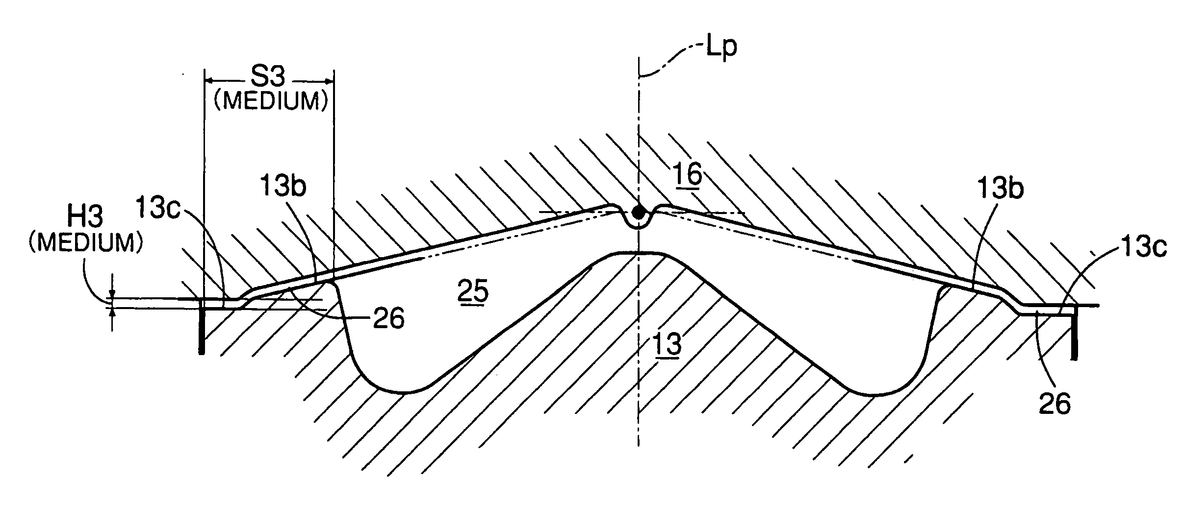
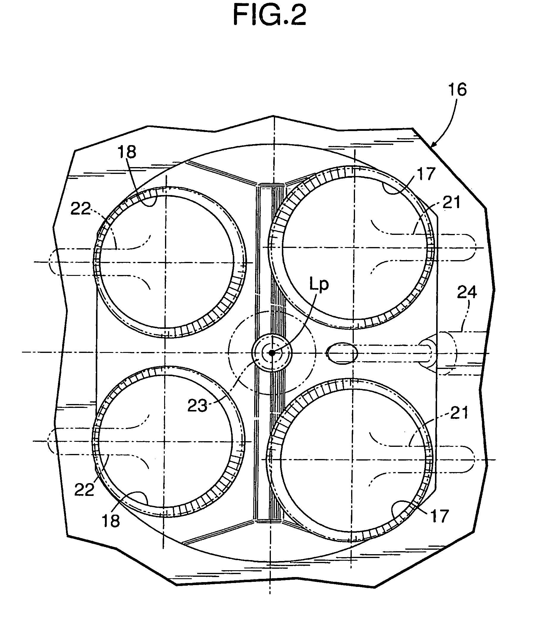
[0029]As shown in FIG. 1 to FIG. 3, a direct fuel injection type diesel engine includes a piston 13 slidably fitted into a cylinder 12 formed in a cylinder block 11, and the piston 13 is connected to a crankshaft (not illustrated) via a piston pin 14 and a connecting rod 15. Two intake valve holes 17 and 17 and two exhaust valve holes 18 and 18 facing a top face of the piston 13 open in a lower face of a cylinder head 16, which is joined to an upper face of the cylinder block 11, an intake port 19 communicates with the intake valve holes 17 and 17, and an exhaust port 20 communicates with the exhaust valve holes 18 and 18. The intake valve holes 17 and 17 are opened and closed by intake valves 21 and 21, and the exhaust valve holes 18 and 18 are opened and closed by exhaust valves 22 and 22. A fuel injector 23 is provided so as to be positioned above a piston central axis Lp, and a glow plug 24 is provided so as...

embodiment 2

[0042]FIG. 8 to FIG. 10 show a second embodiment of the present invention.

[0043]In the second embodiment, a ratio D / B (that is, a width S of a squish area 26) of a cavity entrance diameter D to a cylinder bore diameter B changes in the circumferential direction as in the first embodiment, but the length of a squish clearance H is set so that it is constant in the circumferential direction.

[0044]Instead, formed between a cavity 25 and flat faces 13c and 13c where the width of the squish area 26 becomes a maximum are cutouts 13e and 13e, which are connected to the flat faces 13c and 13c at the same height. By forming the cutouts 13e and 13e in a portion in which squish flow tends to become strong due to a width S of the squish area 26 being large, the squish flow is weakened, thus giving the same effects as those when the squish clearance H is increased, and as in the first embodiment it is possible to make the strength of the squish flow uniform in the circumferential direction, thus...


PUM


Abstract

In a direct fuel injection diesel engine having a piston with a pentroof-shaped top face, with regard to a pentroof-shaped piston (13) with a cavity (25) recessed in a central part of the top face, a radial width S of a squish area (26) formed between an outer peripheral part of the top face and a lower face of a cylinder head (14) changes in the circumferential direction of the piston (13). By setting a squish clearance H large for a portion where the radial width S of the squish area (26) is large and setting the squish clearance H small for a portion where the radial width S of the squish area (26) is small, more specifically, by setting S / H so that it is constant in the circumferential direction, it is possible to make the strength of the squish flow uniform in the circumferential direction of the piston, thus promoting the mixing of air and fuel and reducing harmful exhaust components.

Description

TECHNICAL FIELD[0001]The present invention relates to a direct fuel injection diesel engine that includes a piston for which the height of a top face changes in the circumferential direction, and a fuel injector for injecting fuel into a cavity recessed in a central part of the piston, a ratio D / B of a cavity entrance diameter D to a cylinder bore diameter B in a plane perpendicular to a piston central axis changing in the circumferential direction.BACKGROUND ART[0002]In general, the top face of a piston of a direct fuel injection diesel engine is formed flat, but a direct fuel injection diesel engine for which the top face of a piston projects in a pentroof shape is known from Patent Publication 1 below.[0003]When the top face of a piston is formed flat, the strength of a squish flow heading from a squish area of an outer peripheral part of the top face of the piston toward a cavity recessed in a central part of the piston is uniform in the circumferential direction. However, with ...

Claims


Application Information

Patent Timeline
IPC IPC(8): F02F3/24F02B23/00
CPCF02B3/06F02B23/0621F02B23/0657F02B23/0669Y02T10/123F02B2275/14F02F1/242Y02T10/125F02B23/0696Y02T10/12
Inventor SHIBATA, MITSUHIROSONO, HIROSHISASAKI, NOBUHIKOUCHIMOTO, TATSUYAIKEYA, KENICHIROTAJIMA, YUTAKAYAMAYA, YUKIHISA
Owner HONDA MOTOR CO LTD
Learn More