
Pneumatic tire and manufacturing method of pneumatic tire

a pneumatic tire and manufacturing method technology, applied in the field of pneumatic tire and pneumatic tire manufacturing method, can solve the problems of insufficient conductivity, radio noise, earth to the human body, etc., and achieve the effect of excellent conductive performan

Inactive Publication Date: 2010-01-14
TOYO TIRE & RUBBER CO LTD
View PDF9 Cites 19 Cited by
  • Summary
  • Abstract
  • Description
  • Claims
  • Application Information

AI Technical Summary

Benefits of technology

[0015]Accordingly, the non-conductive rubber ribbon is formed in various cross sectional shapes per a winding position, and the conductive layer provided in a part thereof is scattered at various positions in the tire width direction and various heights of the tire cross section in an inner portion of the non-conductive rubber layer. As a result, even if the conductive layer exposed on the tread surface is worn, the other portions tend to be exposed next to the layer. Accordingly, even in the case where an irregular wear is generated, an exposure of the conductive layer on the tread surface can be preferably secure, so that it is possible to achieve an excellent conductive performance.
[0038]In accordance with the method mentioned above, it is possible to continuously and spirally extend the conductive layer along the tire circumferential direction in the inner portion of the non-conductive rubber layer by setting the conductive layer along the longitudinal direction while changing the position in the width direction with respect to the non-conductive rubber ribbon, and it is possible to arrange the conductive layer at various positions in the tire width direction and at various heights of the tire cross section while effectively increasing the degree of the scattering of the conductive layer mentioned above. As a result, it is possible to secure the exposure frequency of the conductive layer on the tread surface, and it is possible to manufacture the pneumatic tire achieving the excellent conductivity.

Problems solved by technology

However, the tread rubber mentioned above has a higher electric resistance in comparison with the tread rubber in which only the carbon black is compounded, and has a problem that if a static electricity and an electricity generated by an internal friction at a time when a rubber is deformed or the like are accumulated in a vehicle body, there is generated a problem such as an earth to the human body, a radio noise or the like.
However, in the tire mentioned above, there is a problem that a forming position of the conductive layer is affected by a pattern design, and there is a case where a conductivity is insufficient in the other pattern designs than the rib pattern continuously extending in the tire circumferential direction.
Further, in the case where the conductive layers mentioned above are formed at plural numbers, there is a problem that a manufacturing step becomes complicated.
However, in the tire mentioned above, there is a case where the conductive performance cannot be sufficiently achieved in some wear state of the tread rubber such as a case where only a shoulder is worn in an early stage.
However, in the tire mentioned above, since the conductive rubber layer is continuously exposed onto the tread surface in correspondence to the wear state as well as a rate of the conductive rubber is increased more than necessary, there is a case where the good mileage and the wet performance corresponding to an original purpose cannot be achieved.
However, in the tire mentioned above, there is a case where the conductive rubber exposed on the tread surface is extremely reduced in some wear state of the tread rubber, and there is a risk that the conductive performance cannot be sufficiently secured.
Further, there is a tendency that a manufacturing step is complicated and a productivity is lowered.

Method used


Image

  • Pneumatic tire and manufacturing method of pneumatic tire
  • Pneumatic tire and manufacturing method of pneumatic tire
  • Pneumatic tire and manufacturing method of pneumatic tire

Examples


first embodiment

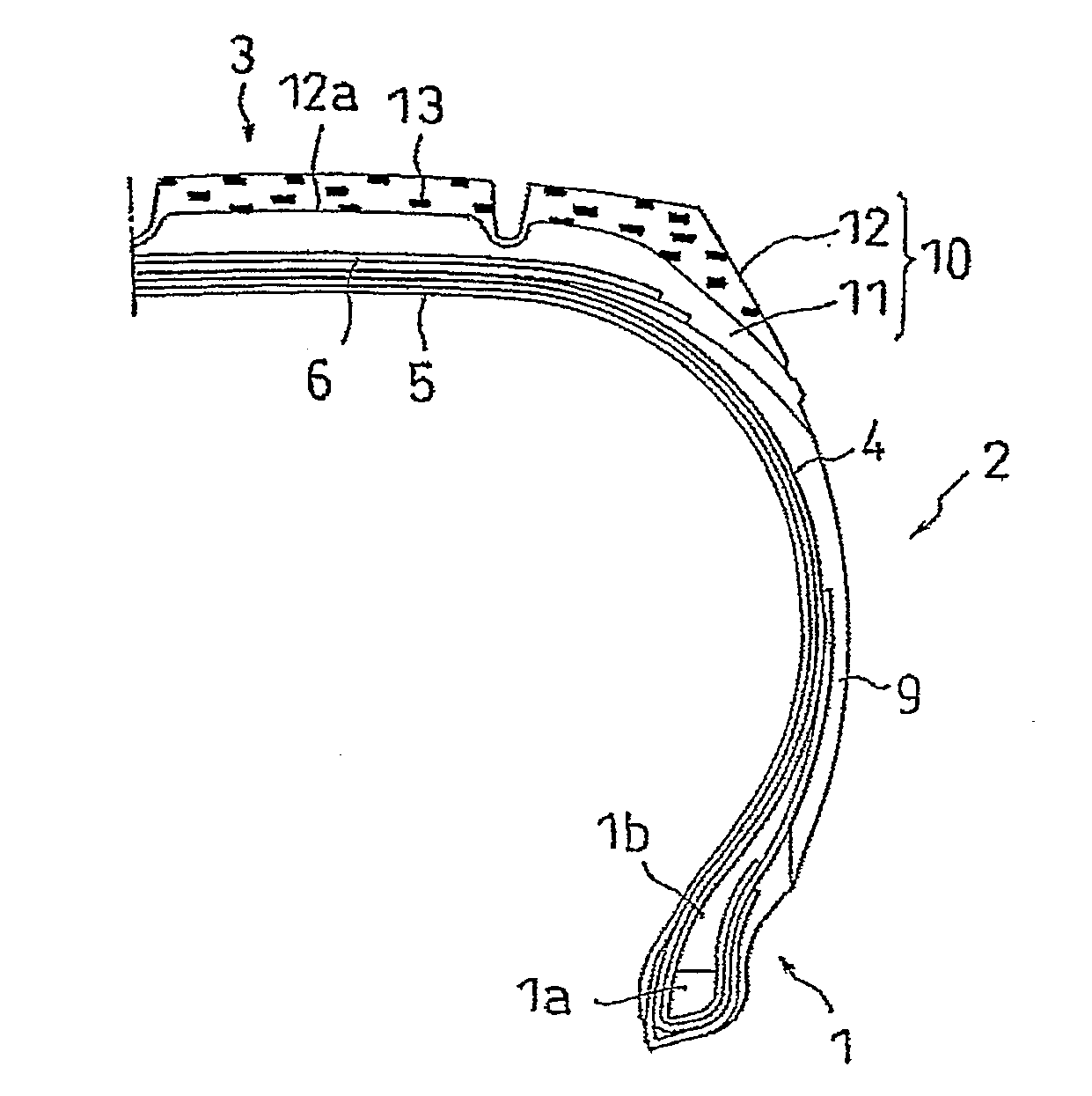
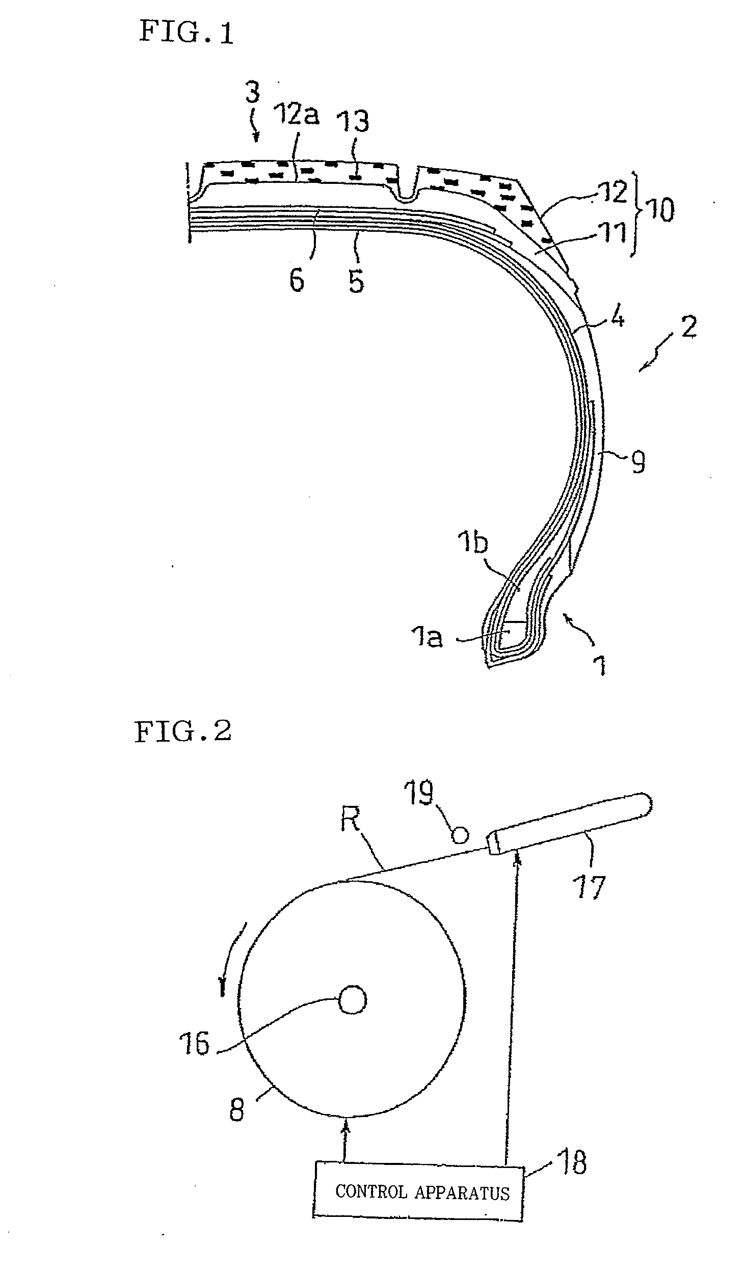
[0072]FIG. 1 is a half cross sectional view of a tire meridian showing an example of a pneumatic tire in accordance with the present invention. This pneumatic tire includes a pair of annular bead portions 1, sidewall portions 2 extending from respective bead portions 1 radially outward of the tire, and a tread portion 3 provided between the sidewall portions 2.

[0073]In the bead portions 1, an annular bead 1a formed by coating a convergence body of steel wire with rubber, and a bead filler 1b made of hard rubber having substantially triangular cross section. Further, a sidewall rubber 9 is arranged in a side wall portion 2, and a tread rubber 10 is arranged in a tread portion 3. A surface of the tread rubber 10 is provided with a main groove extending along a tire circumferential direction, a horizontal groove extending while intersecting the main groove, and the like, and a predetermined tread pattern is formed.

[0074]A portion between the beads 1a is reinforced by a carcass layer 4 ...

second embodiment

[0093]Since a second embodiment has the same structure and operation as those of the first embodiment except the following structures of the tread rubber, a description will be given mainly of different points by omitting the common points. In this case, the same reference numerals are attached to the same members and positions as the already described members and positions in the description of the first embodiment, and an overlapping description will be omitted.

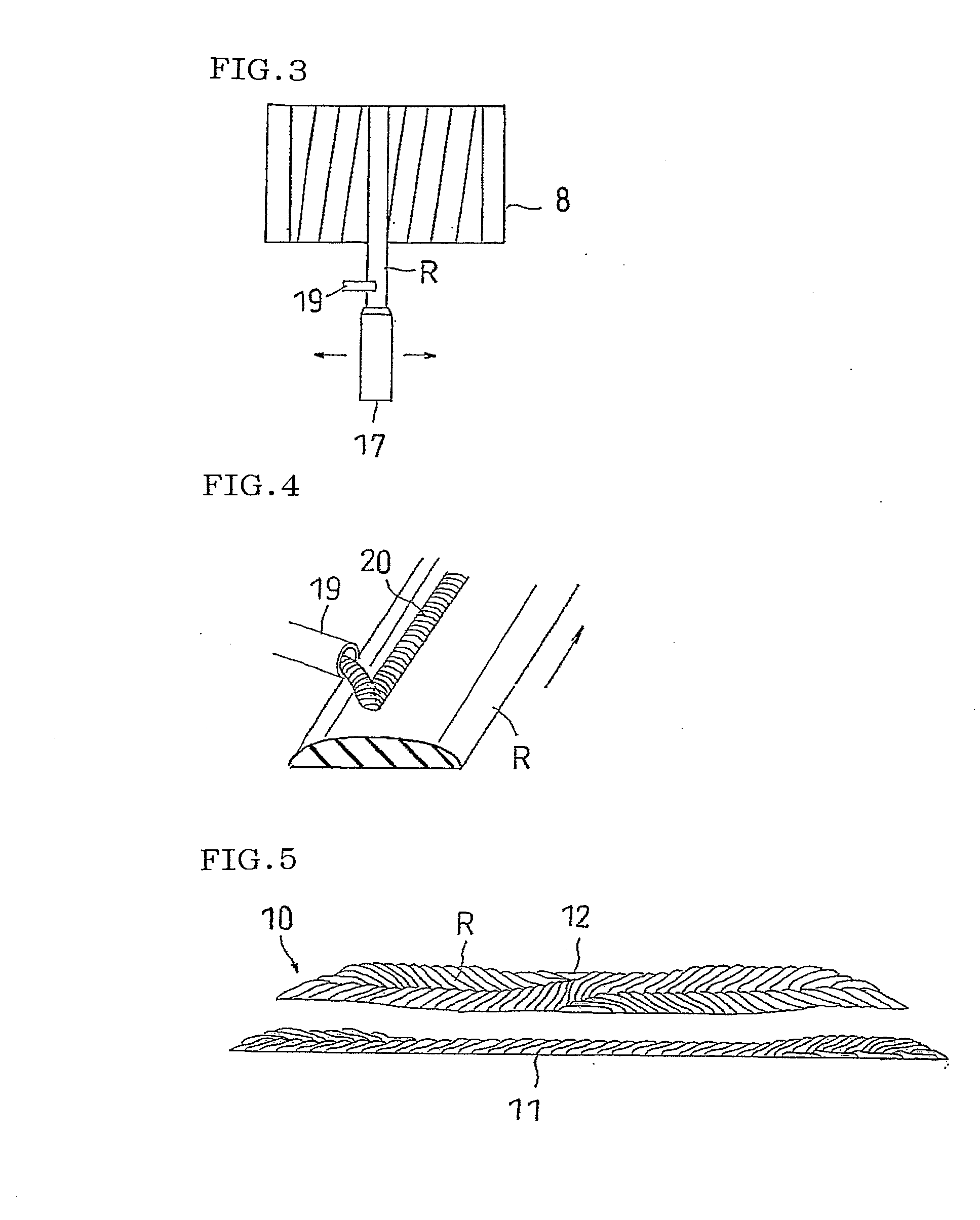
[0094]FIG. 8 is a cross sectional view of a tire meridian schematically showing a tread rubber of a pneumatic tire in accordance with a second embodiment of the present invention. The tread rubber 10 is formed as a cap and base structure provided with the base rubber 11 and the cap rubber 12 (corresponding to the non-conductive rubber layer). The base rubber 11 is formed of a conductive rubber in which a carbon black is compounded as a reinforcing agent at a high rate, and is formed by annularly connecting the conductive ru...

examples 1-1 to 1-4

[0115]Examples 1-1 to 1-4 are set to pneumatic tires in which a tread rubber is constituted by a two-layer structure including a base rubber made of a conductive rubber and a cap rubber made of a non-conductive rubber, and two conductive layers are embedded in the cap rubber as shown in the second embodiment. For forming the cap rubber, there is used a rubber ribbon having a thickness of 2 mm and a rectangular cross sectional shape and formed of a conductive rubber partly (a portion having a thickness of 0.5 mm), and wound in accordance with a procedure shown in the second embodiment. Results are shown in Table 1.

TABLE 1Electric resistance (Ω)EWOWTire of 60%WetRolling(mm)(mm)New tirewearperformanceresistanceComparative——∞∞100100Example 1-1Comparative——1.00E+031.00E+10100100Example 1-2(steady)Example 1-11101.00E+031.00E+03100100Example 1-20.05101.00E+031.00E+10100100(non-steady)Example 1-37101.00E+031.00E+039595Example 1-40.11001.00E+031.00E+10100100(non-steady)

[0116]As shown in Tabl...


PUM


Abstract

In the invention, at least a tire outer circumferential side portion of a tread portion is formed of a non-conductive rubber layer. The non-conductive rubber layer is formed by winding and laminating a non-conductive rubber ribbon along a tire circumferential direction. A conductive layer is provided on an outer circumference of the non-conductive rubber ribbon, and the conductive layer continuously and spirally extends along the tire circumferential direction, and is exposed on a tread surface from a bottom surface of the non-conductive rubber layer toward a tire outer circumferential side. Accordingly, an electricity generated in a vehicle body is discharged to a road through the conductive layer. Since the conductive layer is scattered within the non-conductive rubber layer and exposure on the tread surface is preferably secured, it is possible to achieve an excellent conductivity.

Description

TECHNICAL FIELD[0001]The present invention relates to a pneumatic tire in which a tire outer circumferential side portion of a tread portion is constructed by a non-conductive rubber layer, and a manufacturing method of the pneumatic tire.BACKGROUND ART[0002]Conventionally, for the purpose of reducing a rolling resistance of a tire which has a strong connection to a good mileage of a vehicle, there has been known a pneumatic tire in which a tread rubber is highly compounded with a silica. This is structured by reducing a compounding amount of a carbon black causing a hysteresis loss and compounding the silica alternatively. Accordingly, it is possible to reduce the rolling resistance and achieve the good mileage, and it is possible to increase a braking force on a wet road so as to improve a wet performance.[0003]However, the tread rubber mentioned above has a higher electric resistance in comparison with the tread rubber in which only the carbon black is compounded, and has a probl...

Claims


Application Information

Patent Timeline
IPC IPC(8): B60C19/08B29D30/08
CPCB29D30/60B60C19/08B29D2030/526Y10S152/02
Inventor ASAYAMA, YOSHINORIAZUMA, EIJI
Owner TOYO TIRE & RUBBER CO LTD
Features
  • Generate Ideas
  • Intellectual Property
  • Life Sciences
  • Materials
  • Tech Scout
  • Unparalleled Data Quality
  • Higher Quality Content
  • 60% Fewer Hallucinations
Learn More