Apparatus for generating hollow cathode plasma and apparatus for treating large area substrate using hollow cathode plasma
- Summary
- Abstract
- Description
- Claims
- Application Information
AI Technical Summary
Benefits of technology
Problems solved by technology
Method used
Image
Examples
first embodiment
[0072]An apparatus for treating a large area substrate using hollow cathode plasma according to the present invention will now be described.
[0073]FIG. 4 is a cross-sectional view of an apparatus for treating a large area substrate using hollow cathode plasma according to a first embodiment of the present invention. Referring to FIG. 4, a substrate treatment apparatus 100 of the present invention includes a process chamber 110, a gas supply member 120, a substrate support member 130, a hollow cathode 140, a baffle 150, and a power supply source 170.
[0074]The process chamber 110 provides a space in which a substrate treatment process is performed. An exhaust hole 111 for exhausting gases is defined in a bottom surface of process chamber 110. The exhaust hole 111 is connected to an exhaust line in which a pump is installed to exhaust reaction by-products generated inside the process chamber 110 and maintain a process pressure in the process chamber 110. The gas supply member 120 suppli...
second embodiment
[0101]An apparatus for treating a large area substrate using hollow cathode plasma according to the present invention will now be described.
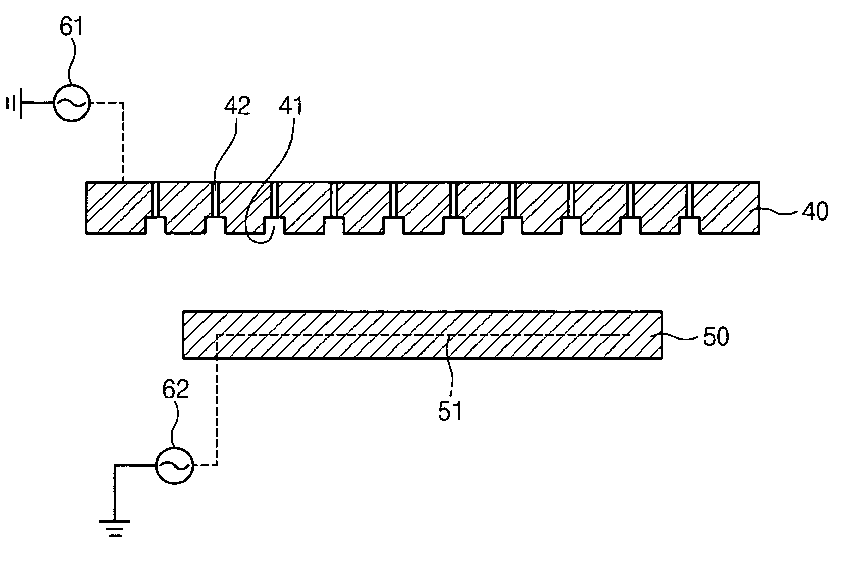
[0102]FIG. 5 is a cross-sectional view of an apparatus for treating a large area substrate using hollow cathode plasma according to a second embodiment of the present invention. Referring to FIG. 5, an apparatus 200 for treating a large area substrate using hollow cathode plasma of the present invention includes a process chamber 210, a gas supply member 220, a substrate support member 230, a hollow cathode 240, a baffle 250, a lower electrode 260, and power supply sources 271 and 272.
[0103]The process chamber 210 provides a space in which a substrate treatment process is performed. An exhaust hole 211 for exhausting gases is defined in a bottom surface of process chamber 210. The exhaust hole 211 is connected to an exhaust line in which a pump is installed to exhaust reaction by-products generated inside the process chamber 210 and maintains a ...
third embodiment
[0116]An apparatus for treating a large area substrate using hollow cathode plasma according to the present invention will now be described.
[0117]FIG. 6 is a cross-sectional view of an apparatus for treating a large area substrate using hollow cathode plasma according to a third embodiment of the present invention. Referring to FIG. 6, an apparatus 300 of treating a large area substrate using hollow cathode plasma includes a process chamber 310, a gas supply member 320, a substrate support member 330, a hollow cathode 340, a baffle 350, a lower electrode 360, and power supply sources 371 and 372.
[0118]The process chamber 310 provides a space in which a substrate treatment process is performed.
[0119]An exhaust hole 311 for exhausting gases is defined in a bottom surface of process chamber 310. The gas supply member 320 supplies the gases into the process chamber 310.
[0120]The substrate support member 330 supports a substrate W, and the lower electrode 260 is provided inside the subst...
PUM
| Property | Measurement | Unit |
|---|---|---|
| Diameter | aaaaa | aaaaa |
| Diameter | aaaaa | aaaaa |
| Diameter | aaaaa | aaaaa |
Abstract
Description
Claims
Application Information
 - R&D
- Intellectual Property
- Life Sciences
- Materials
- Tech Scout
- Unparalleled Data Quality
- Higher Quality Content
- 60% Fewer Hallucinations
Browse by: Latest US Patents, China's latest patents, Technical Efficacy Thesaurus, Application Domain, Technology Topic, Popular Technical Reports.
© 2025 PatSnap. All rights reserved.Legal|Privacy policy|Modern Slavery Act Transparency Statement|Sitemap|About US| Contact US: help@patsnap.com


