Method and apparatus for thin film quality control

a technology of thin film and quality control, applied in the field of thin film quality control, can solve the problem that the continuous production process cannot be stopped, and achieve the effect of preventing the process from being stopped

Inactive Publication Date: 2010-01-14
BRIGHTVIEW SYST LTD
View PDF3 Cites 16 Cited by
  • Summary
  • Abstract
  • Description
  • Claims
  • Application Information

AI Technical Summary

Benefits of technology

[0006]A method and apparatus for a photovoltaic thin film quality control where the thin film is supported by a support and a section of the film is illuminated by a polychromatic illumination source. The source forms on the thin film a continuous illuminated line. A sampling unit samples a plurality of discrete sampled points located on the illuminated line and images the points onto a two dimensional optical switch. A control unit with the help of a calibration scanner generates a concordance look-up-table between the coordinates of the above sampled points on the thin film and their coordinates on the two dimensional optical switch. A single detector samples all of the points by optically switching between the points and determines the spectral composition of the illumination reflected by the sampled points. The photovoltaic thin film parameters applicable to the quality control are derived from the spectral composition of reflected or transmitted by the photovoltaic thin film illumination.

Problems solved by technology

The continuous production process does not allow the process to be stopped, and panel quality control off-line to be performed as in other thin film industries.

Method used


Image

  • Method and apparatus for thin film quality control
  • Method and apparatus for thin film quality control
  • Method and apparatus for thin film quality control

Examples


Embodiment Construction

[0024]In the following detailed description, for purposes of explanation only, numerous specific details are set forth in order to provide a thorough understanding of the present system and method. It will be apparent, however, that the present system and method may be practiced without these specific details. In other instances, well-known structures and devices are schematically shown in order to simplify the drawings.

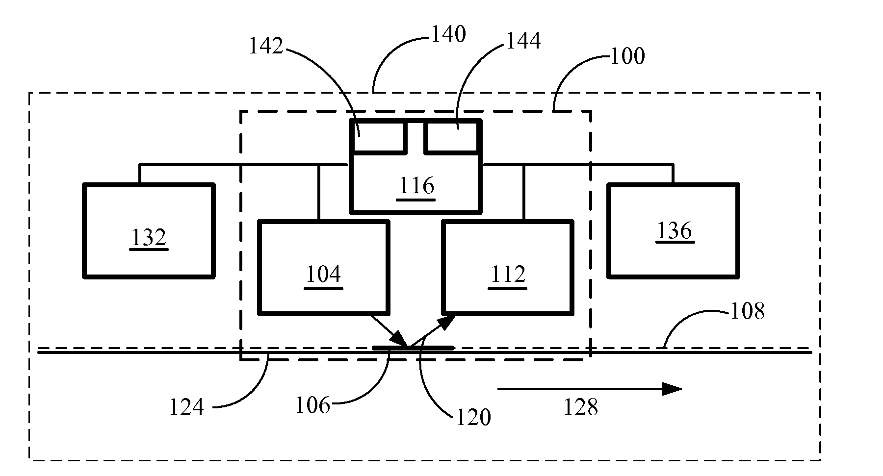
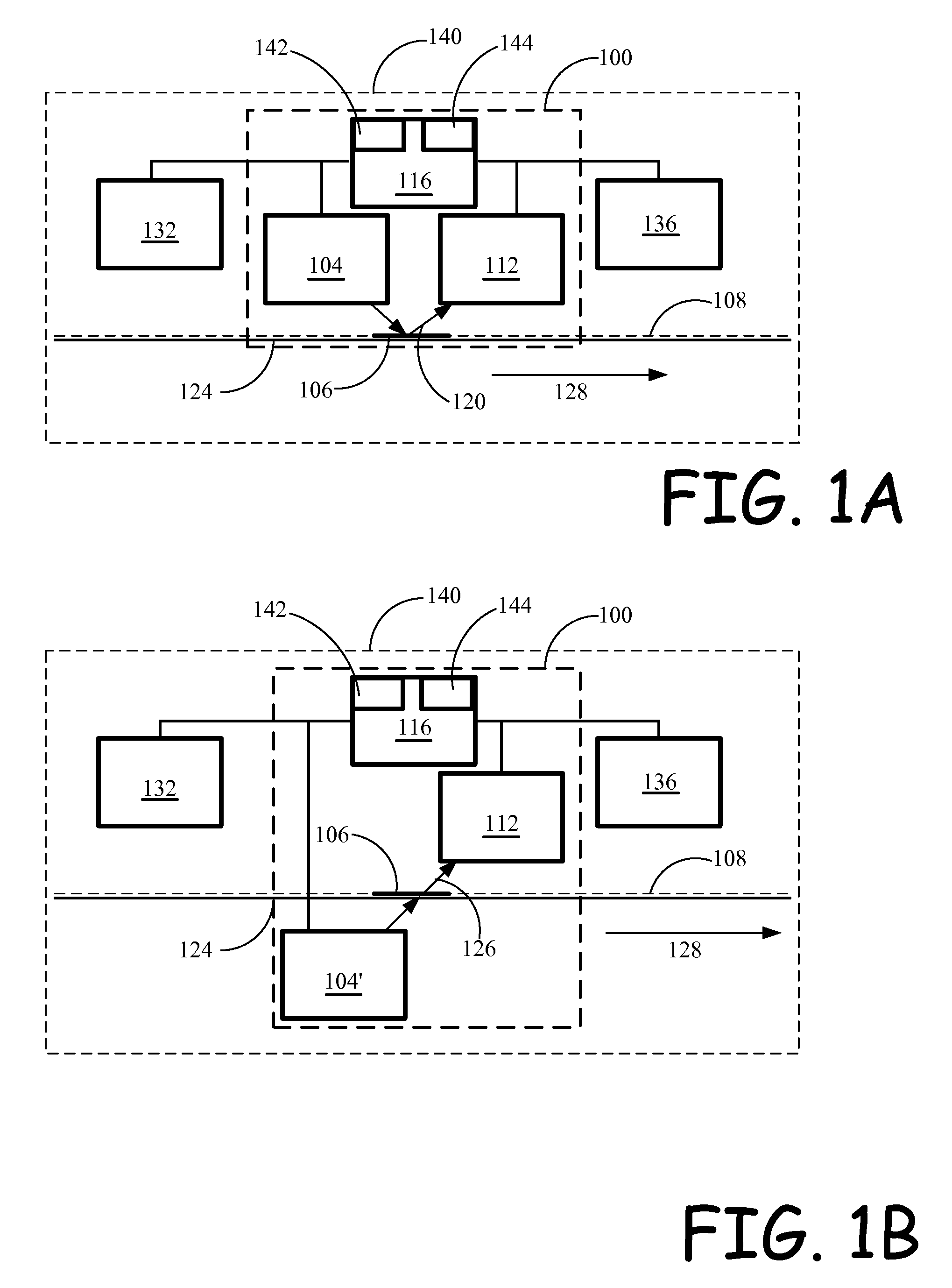
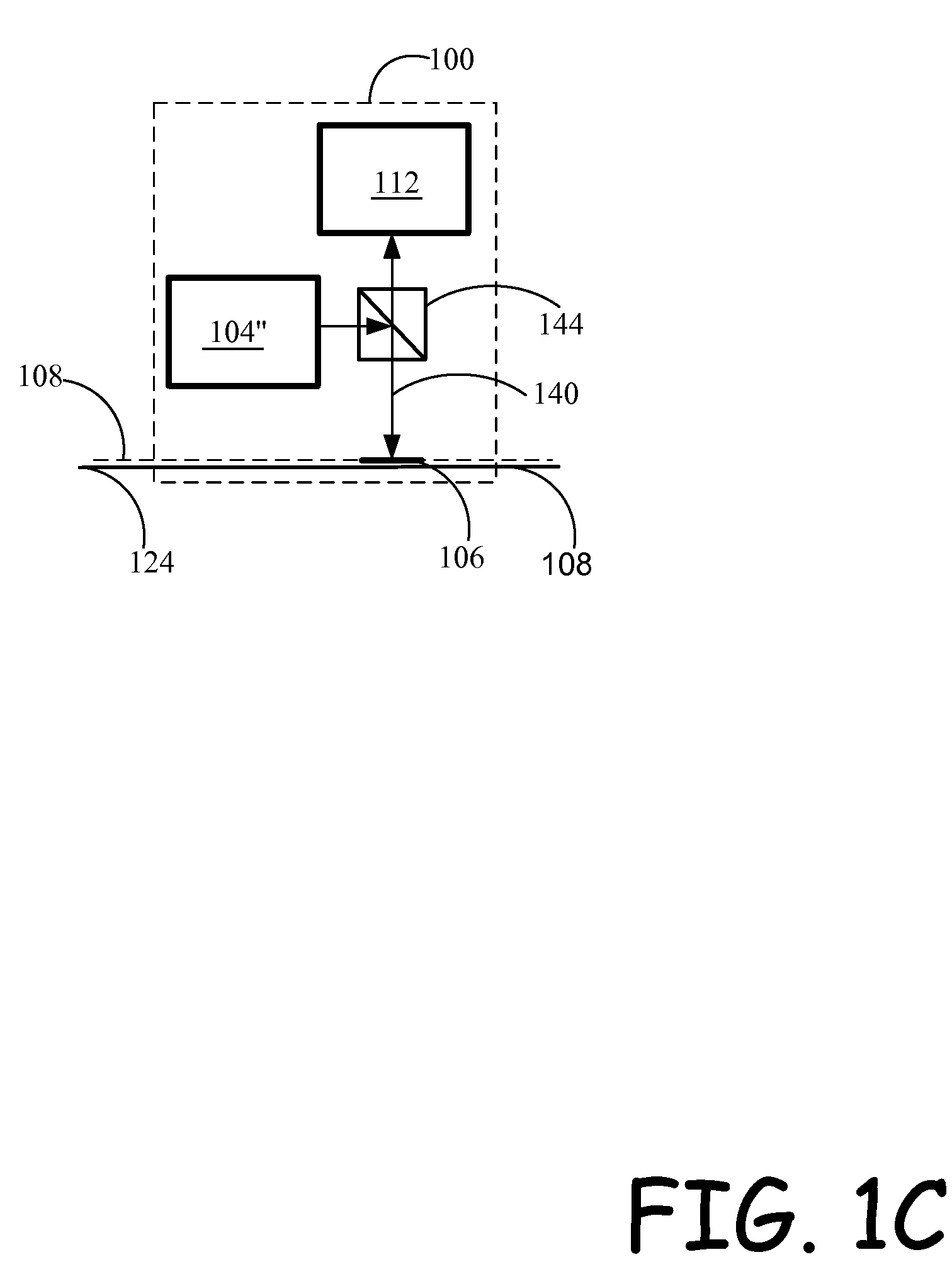
[0025]Reference is made to FIG. 1A, which is a schematic illustration of an exemplary embodiment of the present system for thin film parameters quality control. System 100 includes one or more polychromatic illumination units 104 configured and operative to illuminate an object plane 106, which coincides with a section of the controlled thin film 108; a sampling unit 112 configured and operative to sample multiple discrete points located in the object plane 106 and coinciding with illuminated section of film 108, and a control unit 116 configured and operative to con...


PUM

PropertyMeasurementUnit
timeaaaaaaaaaa
timeaaaaaaaaaa
diameteraaaaaaaaaa

Abstract

Photovoltaic thin film quality control is obtained where the thin film is supported by a support and a section of the film is illuminated by a polychromatic illumination source. The source forms on the thin film a continuous illuminated line. Discrete sampled points located on the illuminated line are imaged onto a two dimensional optical switch. A concordance look-up-table between the coordinates of the above sampled points on the thin film and their coordinates on the two dimensional optical switch are generated. The spectral composition of the illumination reflected by the sampled points is determined and photovoltaic thin film parameters applicable to the quality control are derived from the spectral composition of reflected or transmitted by the photovoltaic thin film illumination.

Description

CROSS-REFERENCE TO RELATED APPLICATIONS[0001]This application, which is a non-provisional application being filed under 37 CFR 1.53(b) and 35 USC 111, claims the benefit of the priority date of the United States Provisional Application for patent filed on Jul. 14, 2008 and assigned Ser. No. 61 / 080,279 and of the United States Provisional Application for patent filed on Oct. 16, 2008 and assigned Ser. No. 61 / 105,931. Both applications are hereby incorporated by reference.TECHNOLOGY FIELD[0002]The method and system relate to the area of thin film quality control and in particular, to the quality and process control in manufacturing thin film photovoltaic cells.BACKGROUND[0003]Scarcity and environmental effects of fossil energy sources that emerged in recent years have accelerated development of alternative energy sources. Thin film photovoltaic solar panels, being one such source have attracted particular attention. These panels represent a number of different thin films (stack) depos...

Claims


Application Information

Patent Timeline
Patent Type & Authority Applications(United States)
IPC IPC(8): G01N21/86G06F19/00
CPCG01N21/31G01N21/6489G01N21/8422G01N21/8901G01N2201/1085G01N2021/8908G01N2201/0826G01N2201/0833G01N2021/3568
Inventor FINAROV, MOSHE
Owner BRIGHTVIEW SYST LTD
Why Eureka
Try Eureka