High-resolution polarization-sensitive imaging sensors

a polarization-sensitive, high-resolution technology, applied in the field of imaging devices, can solve the problems of high rotation speed, inability to capture sequence images in time, maintenance of the mechanism,

Inactive Publication Date: 2000-06-13
THE UNITED STATES OF AMERICA AS REPRESENTED BY THE SECRETARY OF THE NAVY
View PDF26 Cites 111 Cited by
  • Summary
  • Abstract
  • Description
  • Claims
  • Application Information

AI Technical Summary

Problems solved by technology

A fundamental limitation when using thermal intensity for search and identification is that thermal intensity gives one parameter whereas the surface orientation on a three-dimensional object is specified by two angles.
A disadvantage to using a single polarizer is that the mechanism for rotation requires maintenance and is subject to failure during operation.
Another disadvantage is that, because a large aperture polarizer is bulky, a high rotation speed is impractical, which limits how close in time the sequence of images can be captured.
A further disadvantage is that, the substrates on which polarizers are fabricated do not have plane parallel surfaces.
When such substrates are rotated, the image position at the photodetectors will wander, resulting again in misregistration.
Yet another disadvantage is that a sensor with a mechanism for rotating a polarizer at a high rotation speed would be massive and large and not portable.
However, a disadvantage of using the polarizer array in the inventor's patent is that polarization data cannot be captured accurately when objects extend over less than one pixel, i.e. point source objects.

Method used


Image

  • High-resolution polarization-sensitive imaging sensors
  • High-resolution polarization-sensitive imaging sensors
  • High-resolution polarization-sensitive imaging sensors

Examples


Embodiment Construction

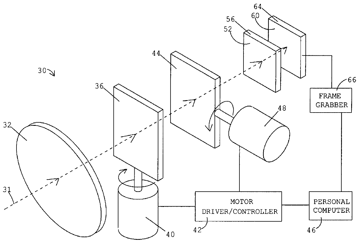
The imaging sensor 30 in FIG. 3 is used to capture data on the Stokes parameters I, Q, and U over the field of view. The sequence of operations for capturing polarization data is shown in FIG. 8. These operations can be entered as a sequence of instructions in a program for the personal computer 46 to execute.

Before this program begins execution, the imaging sensor 30 in FIG. 3 has the following configuration. The focusing lens 32 forms an image of the objects on the focal plane array 60. An individual photodetector in the focal plane array 60 views a object point through the detector's corresponding polarizer. In FIG. 9, the view of polarizer array labeled Frame 1 shows the location of the image 88 of the object point. The image 88 is on a 90.degree. polarizer. Call this the original position of the object point's image.

When the computer program is executed, the first instruction 92 in FIG. 8 is to the frame grabber 66 to capture an image frame, labeled Frame 1. The image frame is ...


PUM

PropertyMeasurementUnit
transparentaaaaaaaaaa
angleaaaaaaaaaa
electromagneticaaaaaaaaaa

Abstract

An apparatus and method to determine the surface orientation of objects in a field of view is provided by utilizing an array of polarizers and a means for microscanning an image of the objects over the polarizer array. In the preferred embodiment, a sequence of three image frames is captured using a focal plane array of photodetectors. Between frames the image is displaced by a distance equal to a polarizer array element. By combining the signals recorded in the three image frames, the intensity, percent of linear polarization, and angle of the polarization plane can be determined for radiation from each point on the object. The intensity can be used to determine the temperature at a corresponding point on the object. The percent of linear polarization and angle of the polarization plane can be used to determine the surface orientation at a corresponding point on the object. Surface orientation data from different points on the object can be combined to determine the object's shape and pose. Images of the Stokes parameters can be captured and viewed at video frequency. In an alternative embodiment, multi-spectral images can be captured for objects with point source resolution. Potential applications are in robotic vision, machine vision, computer vision, remote sensing, and infrared missile seekers. Other applications are detection and recognition of objects, automatic object recognition, and surveillance. This method of sensing is potentially useful in autonomous navigation and obstacle avoidance systems in automobiles and automated manufacturing and quality control systems.

Description

1. Field of the InventionThe invention relates to imaging devices particularly with respect to the detection and recognition of remote objects.2. Description of the Prior ArtThermal imaging sensors are often used to search for and identify objects. These sensors capture the intensity of radiation from the surfaces of the objects. A fundamental limitation when using thermal intensity for search and identification is that thermal intensity gives one parameter whereas the surface orientation on a three-dimensional object is specified by two angles. Information about the two angles of surface orientation is often contained in the polarization of the thermal radiation. Polarization also gives useful information about the surface properties of the object. Man-made objects have unnaturally smooth surfaces, which in turn produces radiation with greater polarization. Natural backgrounds such as grass, trees, dirt, and sand generate radiation that is less polarized.The polarization properties...

Claims


Application Information

Patent Timeline
Patent Type & Authority Patents(United States)
IPC IPC(8): G01N21/21H04N3/15H04N5/33G01J4/04H04N5/372
CPCG01J4/04H04N3/1587G01N21/211H04N5/33G01J5/59H04N25/48
Inventor CHUN, CORNELL SEU LUN
Owner THE UNITED STATES OF AMERICA AS REPRESENTED BY THE SECRETARY OF THE NAVY
Why Eureka
Try Eureka