Signal transmitting device and signal transmitting method

a transmission device and signal technology, applied in the direction of signal generators with optical-mechanical scanning, selective content distribution, television systems, etc., can solve the problems of complex insufficient transmission rate to transmit ultra-high-definition video signals, etc., and achieve the effect of simplifying the constitution of synchronizing processing

Active Publication Date: 2010-01-14
SONY CORP
View PDF4 Cites 34 Cited by
  • Summary
  • Abstract
  • Description
  • Claims
  • Application Information

AI Technical Summary

Benefits of technology

[0009]The present invention is intended to break through the foregoing situation. An object of the present invention is to allow a receiving side to readily perform synchronizing processing of video and audio when an audio signal is transmitted synchronously with a high-definition video signal.
[0020]According to the present invention, an audio signal is appended to a serial digital video signal conformable to the HD-SDI format in a case where: a video signal is mapped into multiple serial digital video signals conformable to the HD-SDI format; and the digital video signals are separated into and transmitted on multiple channels. If the mapping is achieved so that the phase relationship between the video signal on the channel, on which the audio signal is appended, and the audio signal will be nearly identical to the phase relationship between the original input video signal and input audio signal, the synchronous relationship between the video signal and audio signal is sustained. This obviates the necessity of the processing of keeping a synchronous phase among multiple channels into and on which the video signal is separated and transmitted. A constitution for synchronizing processing is simplified.

Problems solved by technology

The transmission rate is therefore not high enough to transmit an ultra-high-definition video signal.
This poses a problem in that a synchronizing processing constitution may become complex.

Method used


Image

  • Signal transmitting device and signal transmitting method
  • Signal transmitting device and signal transmitting method
  • Signal transmitting device and signal transmitting method

Examples


first embodiment

[0052]Referring to FIG. 1 to FIG. 27, the present invention will be described below.

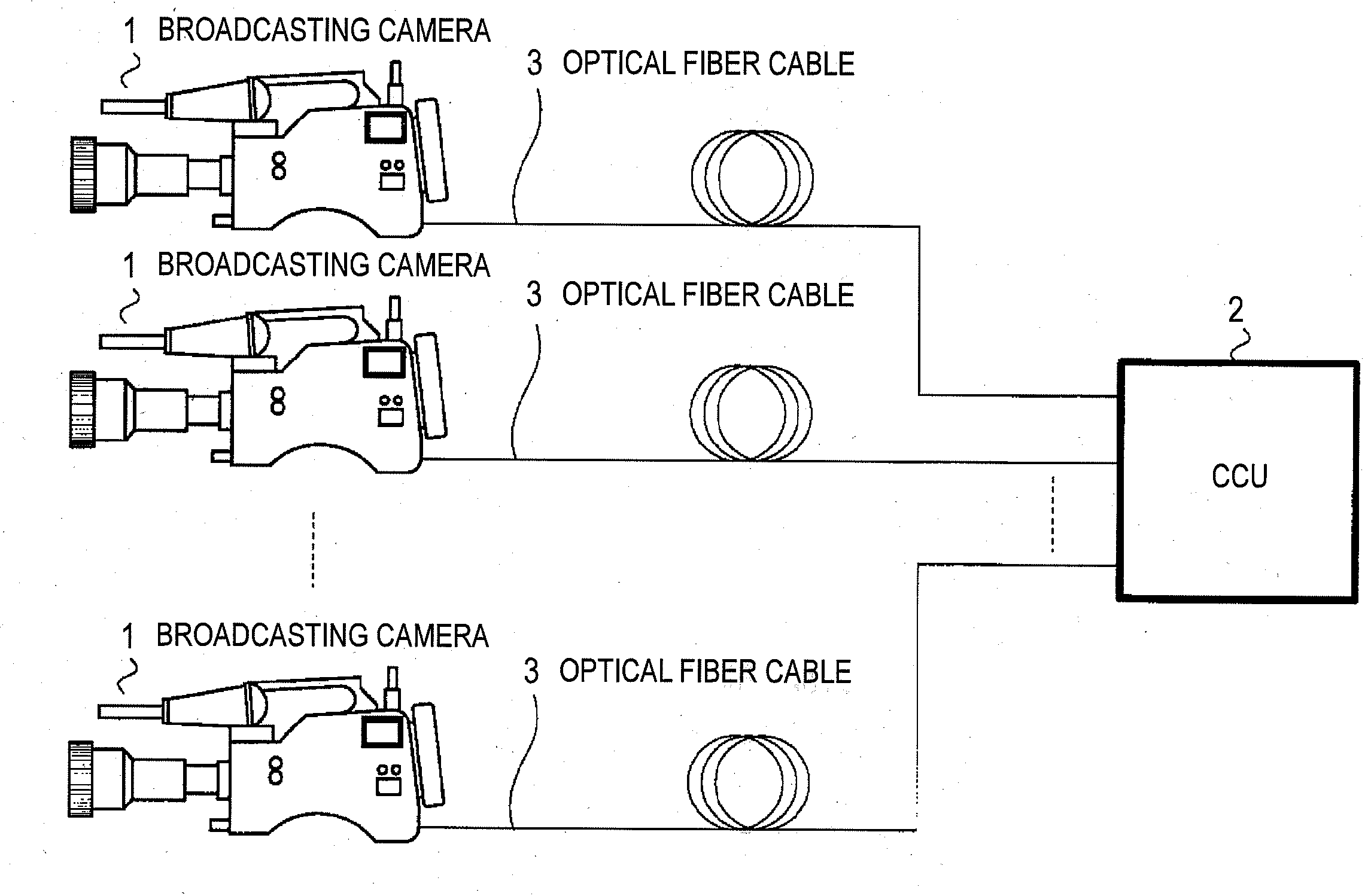
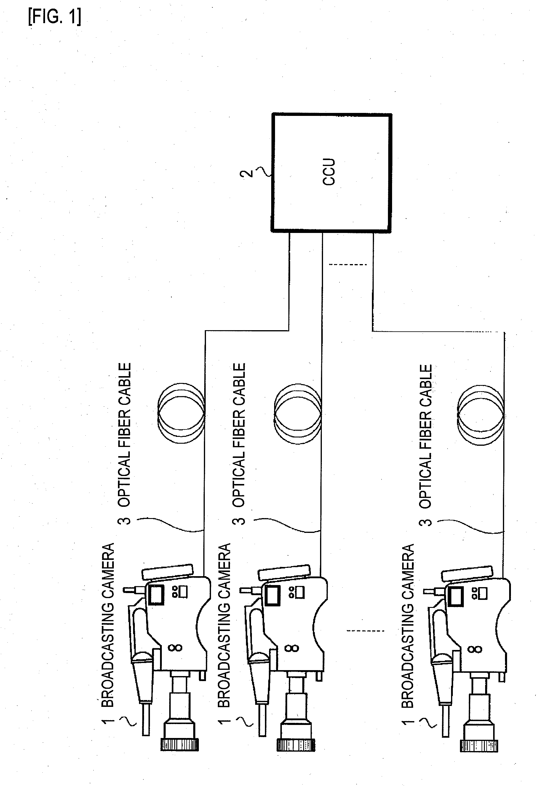
[0053]FIG. 1 is a diagram showing an overall constitution of a camera transmission system for television broadcasting stations to which the present embodiment is adapted. The camera transmission system includes multiple broadcasting cameras 1 and a camera control unit (CCU) 2. The broadcasting cameras 1 are connected to the CCU 2 over optical fiber cables 3.

[0054]The broadcasting cameras 1 are cameras that share the same constitution and function as signal transmitting devices 5 that produce and transmit as a 4 k×2 k signal (an ultra-high-definition signal of 4 k samples×2 k lines) a 3840×2160 / 24P,25P,30P / 4:4:4,4:2:2,4:2:0 / 10,12-bit signal equivalent to an LSDI signal.

[0055]The CCU 2 is a unit that controls each of the broadcasting cameras 1, receives a video signal from each of the broadcasting camera 1, or transmits a video signal (return video) to be used to display on a monitor of each of the bro...

second embodiment

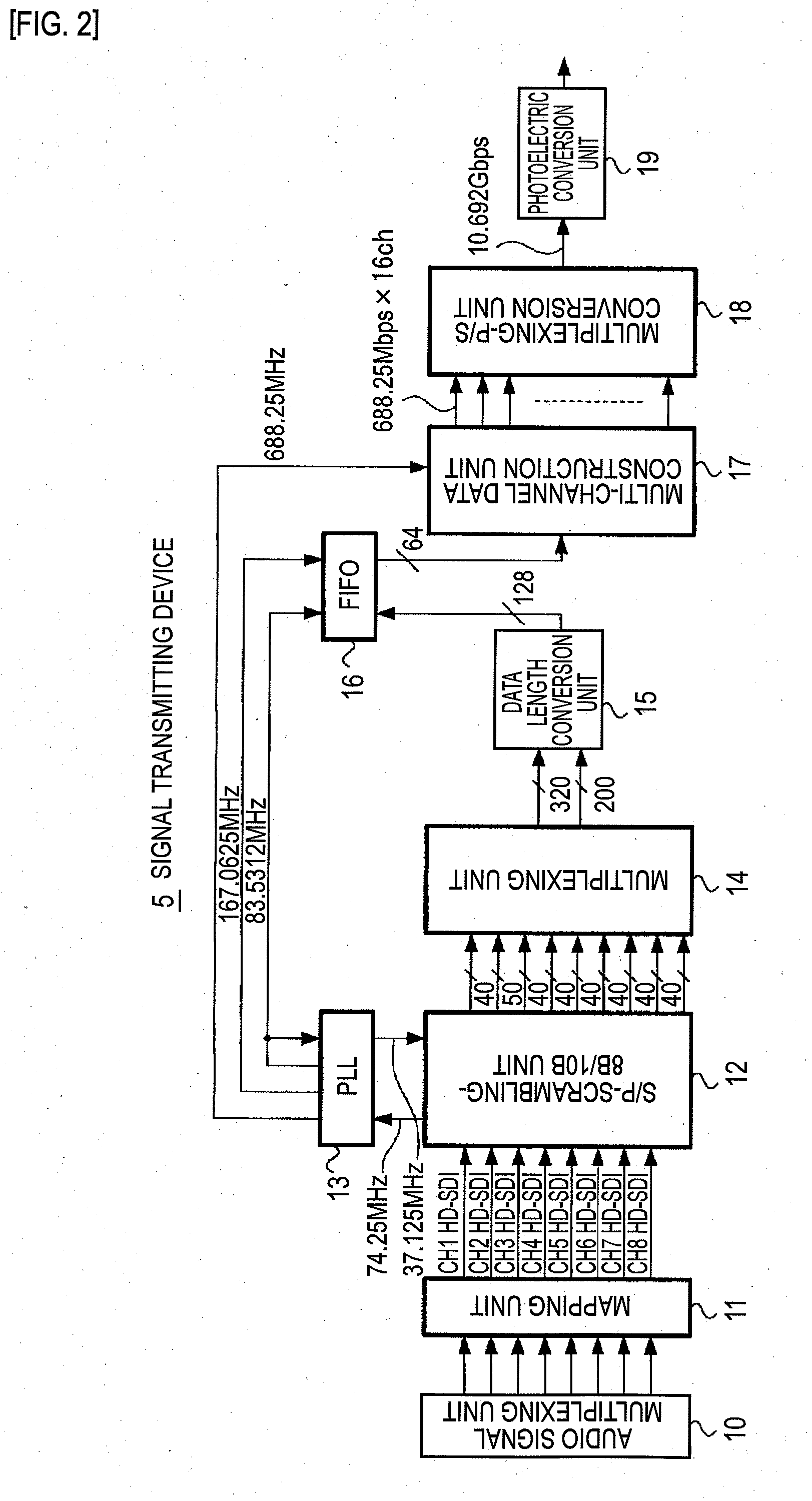
[0275]Next, an example of actions of a mapping unit 11 included in the present invention will be described with reference to FIG. 28.

[0276]FIG. 28 is an explanatory diagram showing an example in which samples constituting one frame of a 4 k×2 k signal are mapped into first to fourth sub-images.

[0277]In the present embodiment, the mapping unit 11 characteristically maps a 3840×2160 / 50P,60P / 4:4:4,4:2:2,4:2:0 / 10,12-bit signal into the first to fourth sub-images, and then converts the sub-images into dual-link data items. The other components are identical to those of the first embodiment. An iterative description will be omitted. As for the processing of a signal receiving device 6 included in a CCU 2, since it is identical to that in the first embodiment, an iterative description will be omitted.

[0278]A broadcasting camera 1 in this example is a camera including a signal transmitting device 5 that produces a 3840×2160 / 50P,60P / 4:4:4,4:2:2,4:2:0 / 10,12-bit signal, which is equivalent to ...

third embodiment

[0296]Next, referring to FIG. 29, an example of actions of a mapping unit 11 included in the present invention will be described.

[0297]FIG. 29 is an explanatory diagram showing an example in which samples constituting one frame of a 8 k×4 k signal are mapped into first to fourth sub-images.

[0298]In the present embodiment, the mapping unit 11 characteristically maps a 7680×4320 / 50P,60P / 4:4:4,4:2:2,4:2:0 / 10,12-bit signal into first to fourth sub-images. The other components are identical to those of the first embodiment. An iterative description will be omitted.

[0299]A broadcasting camera 1 in this example is a camera including a signal transmitting device 5 that produces a first frame, which is specified with a 7680×4320 / 50P,60P / 4:4:4,4:2:2,4:2:0 / 10,12-bit signal equivalent to a UHDTV2 signal, as a frame of a 8 k×4 k signal (an ultra-high-definition signal representing 8 k samples×4 k lines), and transmits HD-SDI signals into which the signal is mapped according to a predetermined me...


PUM


Abstract

Pixels extracted from each of an input video signal are thinned out in units of predetermined samples, and the thinned out samples are fetched in equal order frame by frame and mapped into active periods of first, second, third, and fourth sub-images conformable to the HD-SDI format. The mapped first, second, third, and fourth sub-images are each separated into a first-link transmission channel and a second-link transmission channel, and are thus mapped into eight channels. The mapped first, second, third, and fourth sub-images are converted in parallel. Parallel digital data items into which the sub-images are converted in parallel are then outputted.

Description

TECHNICAL FIELD[0001]The present invention relates to a signal transmitting device and method for serially transmitting a video signal, in which the number of pixels of one frame is equal to or larger than the number of pixels specified in the HD-SDI format, and an audio signal synchronous with the video signal.BACKGROUND ART[0002]Development of an image receiving system and an imaging system that handle an ultra-high-definition video signal which overwhelms a high-definition (HD) signal, that is, an existing video signal (image signal) in which one frame has 1920 samples on each of 1080 lines has made progress. For example, ultra-high-definition television (UHDTV) specifications that constitute a new-generation broadcasting method of handling four times or sixteen times larger the number of pixels than an existing HD broadcasting method have been proposed to or standardized by the International Telecommunication Union (ITU) or the Society of Motion Picture and Television Engineers ...

Claims


Application Information

Patent Timeline
Patent Type & Authority Applications(United States)
IPC IPC(8): H04N7/01H04N5/38H04J3/00H04N5/225H04N7/08H04N7/24H04N7/52
CPCH04N7/015H04N21/4342H04N21/23602H04N7/12H04N5/268H04N23/66H04N23/60
Inventor YAMASHITA, SHIGEYUKI
Owner SONY CORP
Why Eureka
Try Eureka