Lamp

a technology of light and surface, applied in the field of lamps, can solve the problems of difficult to apply techniques, difficult to make an area close to the center function as a light emitting surface, complex construction, etc., and achieve the effect of enlarge the light emitting area

Inactive Publication Date: 2010-01-14
KOITO MFG CO LTD
View PDF13 Cites 80 Cited by
  • Summary
  • Abstract
  • Description
  • Claims
  • Application Information

AI Technical Summary

Benefits of technology

[0014]It is an aspect of the invention to provide a lamp which can enlarge a light emitting area and make a light emitting surface into a three-dimensional plane.

Problems solved by technology

Thus, there is a disadvantage in that it becomes difficult to make an area close to the center function as a light emitting surface.
In view of this disadvantage, in JP-A-2001-297609, separated LED elements or first and second reflecting surfaces for illuminating the central area are required, and accordingly, the resulting construction is complex.
In addition, in the related art lamp described in JP-A-2001-297609, since the light emitting surface of the lamp is limited to the area where the second reflecting surface resides, that is, a plane (a two-dimensional plane) which is orthogonal to the optical axis where the light reflected on the first reflecting area resides, there is a disadvantage in that it becomes difficult to apply the technique described in the JP-A-2001-297609 to, for example, an automotive lamp in which a horizontal right distribution range is made wider than a vertical light distribution range and in which the light emitting surface is curved vertically and horizontally into a three-dimensional plane.
Therefore, there is a disadvantage in that it becomes difficult to obtain a uniform brightness on the light emitting surface.
In addition, since the reflector has a reflecting surface that is approximately flat, the light emitting surface of the lamp is limited to a surface which is close to the two-dimensional surface, and therefore, as has been described before, there is a disadvantage in that the lamp described in JP-A-2003-59313 becomes difficult to be applied in a case where the light emitting surface is curved in a three-dimensional fashion.
In the related art lamp including a light guide plate emission unit like the one described above, there is a disadvantage in that mounting the light emission unit of the light guide plate within the lamp housing is difficult (i.e., it is difficult to form the light guide plate in a flat plate shape).
Moreover, there is an additional disadvantage in that the number of LED elements that may be used are restricted (i.e., it is difficult to introduce the light of LED element from a certain end face of the light guide plate as described in the JP-A-2000-251508).
In such cases, the light has to be introduced into the light guide plate from only part of the end faces of the light guide plate, and as this occurs, guiding light over the whole surface areas of the light guide plate becomes difficult.
Thus, it becomes difficult to illuminate all the surfaces of the light guide plate with uniform brightness.
In addition, in the event that the light guide plate is desired to be a shape other than a rectangular shape, there is a disadvantage in that light from the LED elements has to be guided into the light guide plate only from one of the end faces of the light guide plate.
Thus, the light guide plate cannot be illuminated with uniform brightness over the whole surface area thereof.
Because of this, an uniform lighting state cannot be obtained in the related art lamp with the light guide plate in such a state when the lamp is seen from the front thereof, and therefore, the illumination effect of the lamp is reduced.

Method used


Image

  • Lamp
  • Lamp
  • Lamp

Examples


first exemplary embodiment

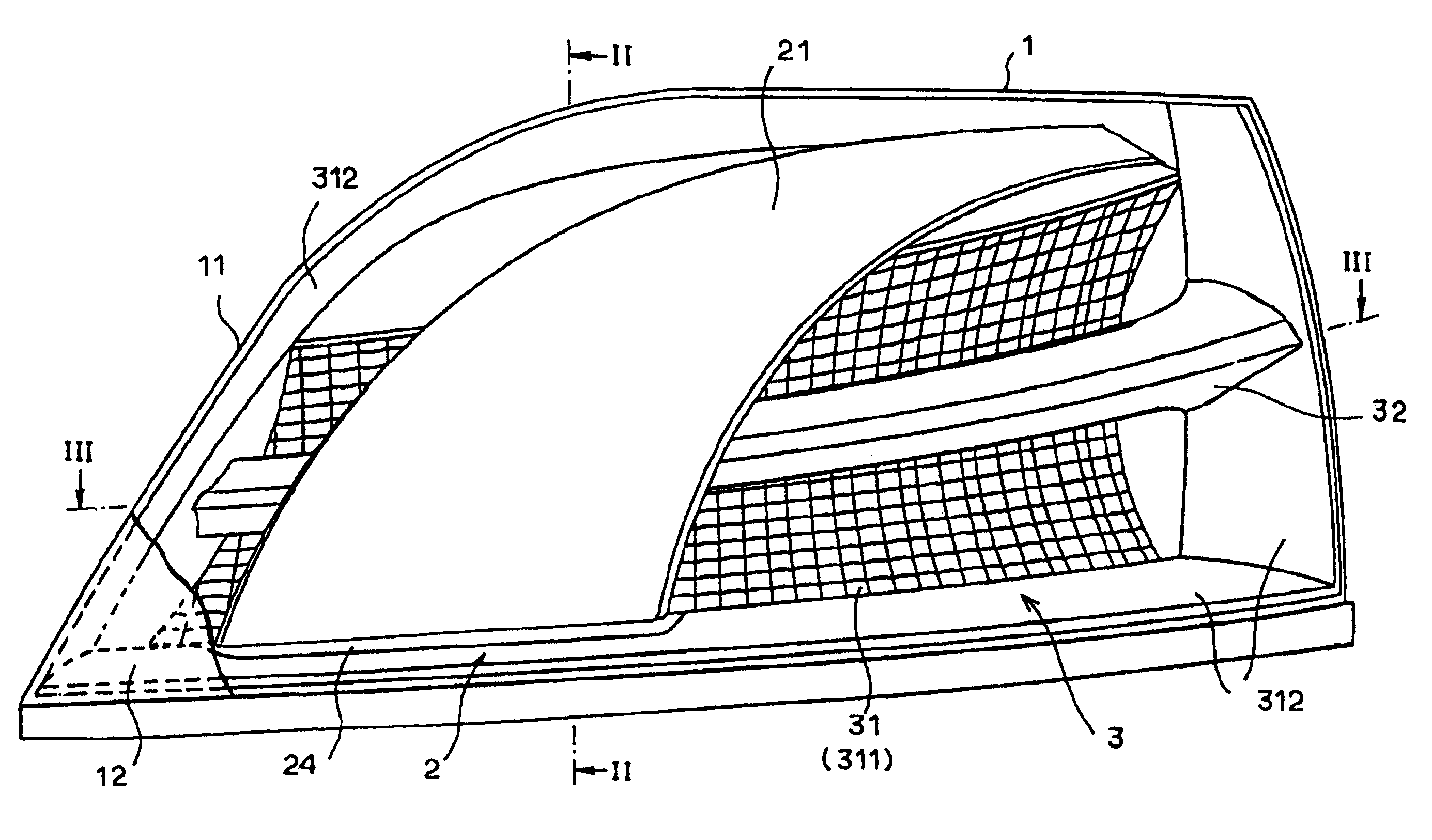
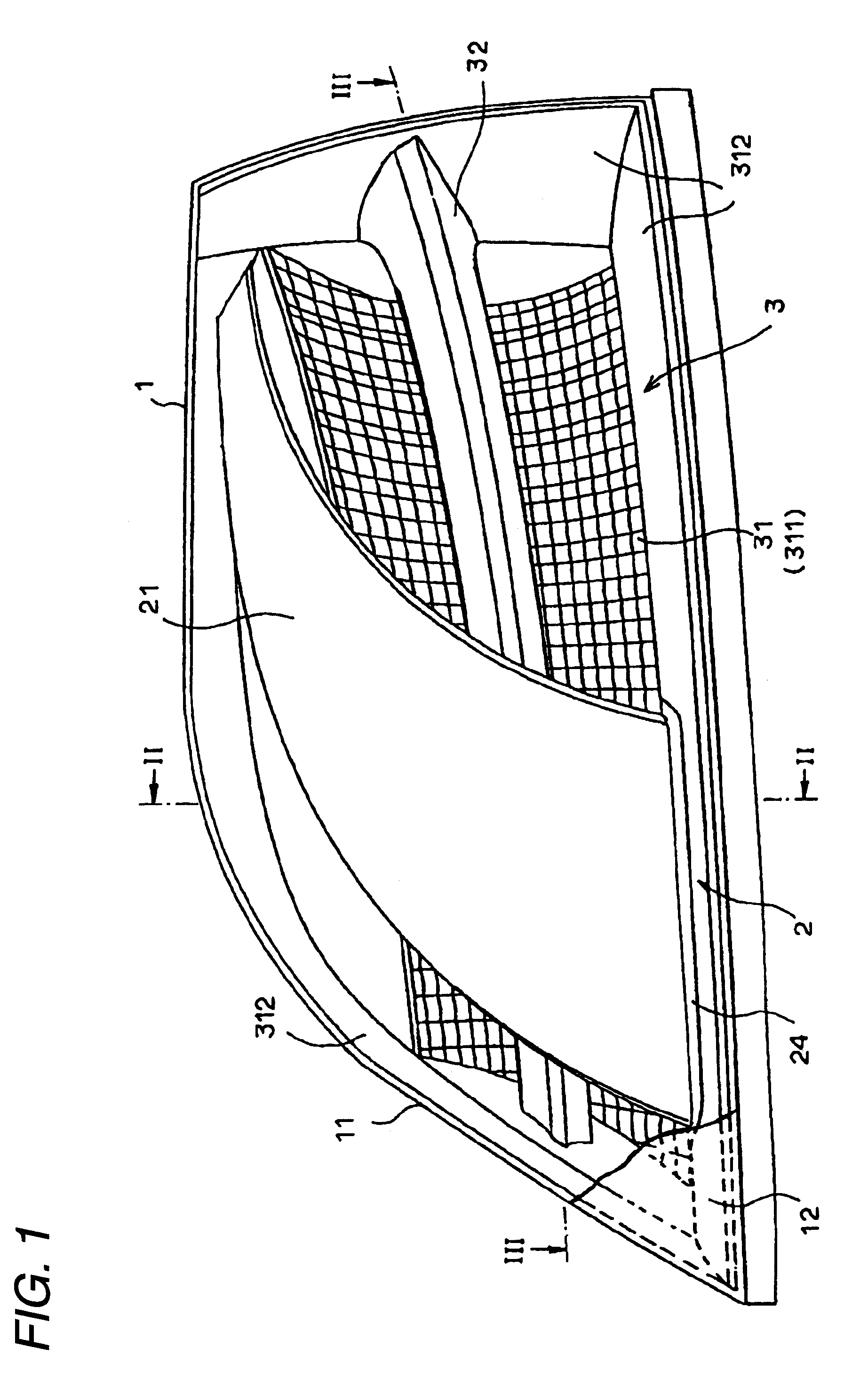
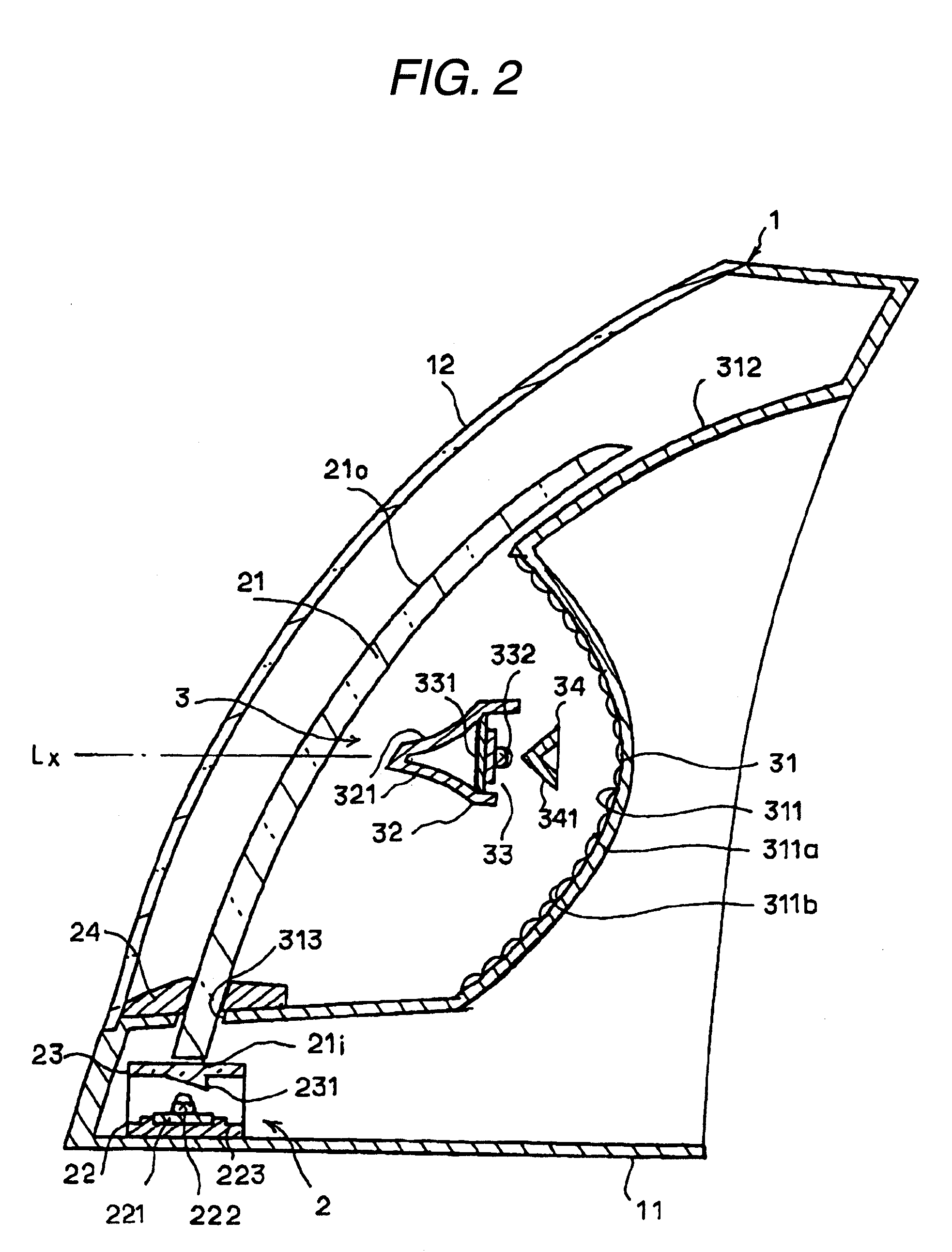
[0042]Next, a first exemplary embodiment of the invention will be described. In FIGS. 1 through 3, a lamp housing 1 includes a lamp body 11 which can be mounted on a right-hand side of a rear part of a vehicle body and which has a vessel-like shape which is made to open in a front surface (a front side) thereof. The lamp housing 1 also includes a transparent front cover 12 which is attached to the front opening. The front cover 12 has a curved shape which projects to the front or in a left-right direction so as to follow the rounded shape of the vehicle body so as to configure part of the vehicle body shape of the vehicle. The lamp of the first exemplary embodiment is configured as a multi-function lamp having a tail lamp function and a stop lamp function. Accordingly, integrally incorporated within the lamp housing 1 are a light guide plate emission unit 2 (a first light emitting unit) which is made into a tail lamp which is lit while the vehicle is driven during night time and a r...

second exemplary embodiment

[0075]While in the first exemplary embodiment, the light emission surface of the light guide plate is illustrated as having a configuration in which the light emission surface is curved curvilinearly from the bottom left area to the top right and rearward area when the tail lamp is seen from the front, the invention can be applied equally in the event that the configuration of the optical steps is changed to match a different front surface configuration of the light guide plate. For example, a light guide plate 21A according to a second exemplary embodiment shown in FIG. 9A has a configuration in which the light guide plate 21 is nearly symmetrical in a horizontal direction and is curved in a three-dimensional direction in such a manner that the width dimension of the light guide plate 21 is gradually reduced from a lower portion towards an upper portion. In the case of the light guide plate 21A, an optical step at a central portion of a stepped plate 23A has a configuration in whic...

third exemplary embodiment

[0076]Alternately, in a third exemplary embodiment shown in FIG. 9B, a light guide plate 21B is formed as having a configuration in which the light guide plate 21B is curved in a three-dimensional direction in such a way as to extend obliquely with a substantially equal width dimension. In the case of the light guide plate 21B, individual optical steps on a stepped plate 23B may be formed to have the same configuration so that light is refracted in the same direction. In the case of the third exemplary embodiment, since the optical steps do not have to be formed to have the serrated configuration, the stepped plate 32B is configured as a simple tapered plate.


PUM


Abstract

A lamp is provided. The lamp includes a lamp housing; light emitting diodes (LEDs); a main reflector disposed so as to oppose to the LEDs for reflecting light emitted from the LEDs towards a front side of the lamp; a sub-reflector which is interposed between the LEDs and the main reflector, and which reflects and diffuses the light emitted from the LEDs towards the main reflector; an LED element assembly which extends in parallel with the sub-reflector and comprises a plurality of flat portions, each flat portion corresponding to one of the plurality of LEDs and on which the corresponding LED is mounted, adjacent ones of the flat portions being coupled together by at least one step portion; and a center portion which covers the LED element assembly and the LEDs such that the LEDs are not exposed to the front side of the lamp.

Description

BACKGROUND OF THE INVENTION[0001]1. Field of the Invention[0002]Apparatuses and devices consistent with the present invention relate to lamps and, more particularly, to lamps that use light emitting diodes (LEDs) as a light source and / or use light guide plates.[0003]2. Description of Related Art[0004]Lamps employing LED elements as a light source have been proposed as lamps for vehicles in recent years. When compared with incandescent lamps, the LED element is advantageous in reducing the consumed power. However, since the output angle at which light is outputted from the LED element is small, when LED elements are used for a vehicle lamp, the LED elements need to be arranged so as to increase the light emitting area of the lamp.[0005]For example, a related art lamp described in Japanese Patent Unexamined Publication JP-A-2001-297609 includes a substantially circular reflector which has first and second reflecting surfaces for reflecting sequentially light emitted from LED elements....

Claims


Application Information

Patent Timeline
Patent Type & Authority Applications(United States)
IPC IPC(8): F21V1/00
CPCB60Q1/0058G02B6/0073F21S48/1335F21S48/215F21S48/2212F21S48/2243F21S48/2268F21S48/2281F21S48/23F21S48/24F21S48/25F21V7/0008F21W2101/14F21Y2101/02G02B6/0025G02B6/0043G02B6/0046G02B6/0068B60Q1/2607F21Y2115/10F21S41/323F21S43/14F21S43/26F21S43/239F21S43/245F21S43/249F21S43/30F21S43/40F21S43/50F21W2103/10F21W2103/35F21W2103/00
Inventor KOIZUMI, HIROYAMOCHIZUKI, MIKI
Owner KOITO MFG CO LTD
Why Eureka
Try Eureka