Video encoding techniques

a technology applied in the field of video encoding and decoding, can solve the problems of reducing picture quality and achieving goals that tend to confli

Inactive Publication Date: 2010-01-14
INTEL CORP
View PDF4 Cites 40 Cited by
  • Summary
  • Abstract
  • Description
  • Claims
  • Application Information

AI Technical Summary

Problems solved by technology

Conventional video encoding algorithms result in losses.
That is, in the course of compressing the video information, some information may be lost, resulting in decreased picture quality.
However, these two goals tend to conflict with one another.

Method used


Image

  • Video encoding techniques
  • Video encoding techniques
  • Video encoding techniques

Examples


Embodiment Construction

[0013]Reference throughout this specification to “one embodiment” or “an embodiment” means that a particular feature, structure, or characteristic described in connection with the embodiment is included in at least one embodiment of the present invention. Thus, the appearances of the phrase “in one embodiment” or “an embodiment” in various places throughout this specification are not necessarily all referring to the same embodiment. Furthermore, the particular features, structures, or characteristics may be combined in one or more embodiments.

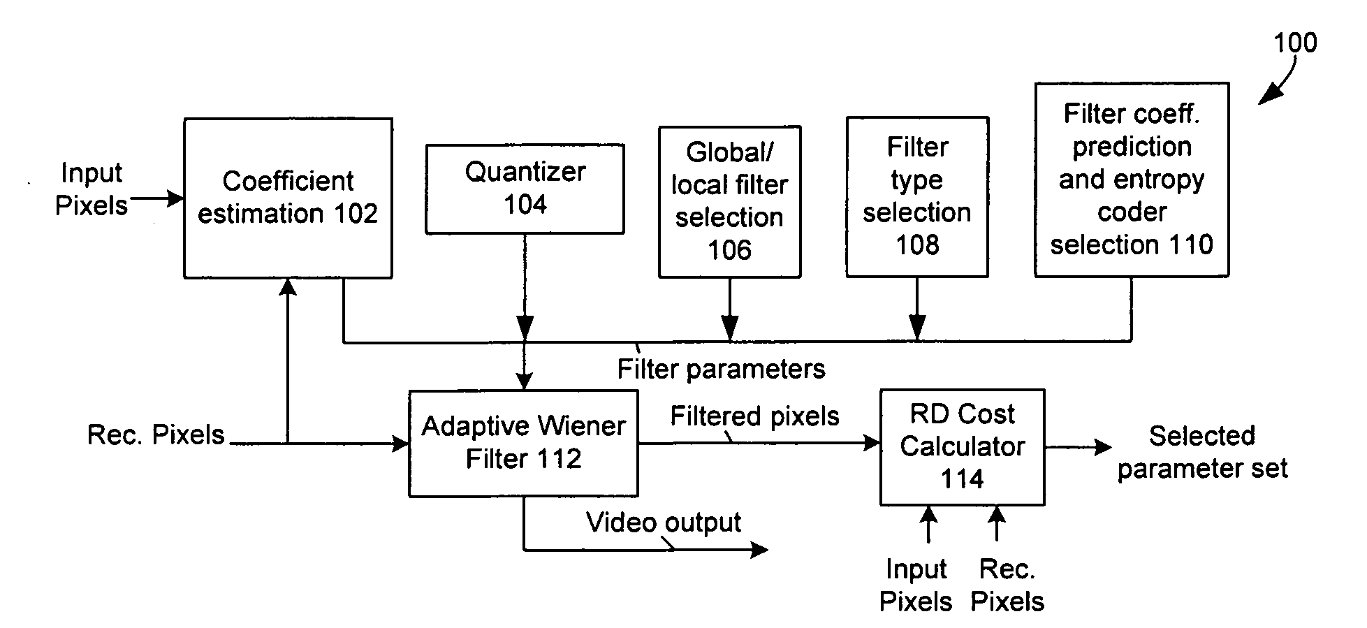
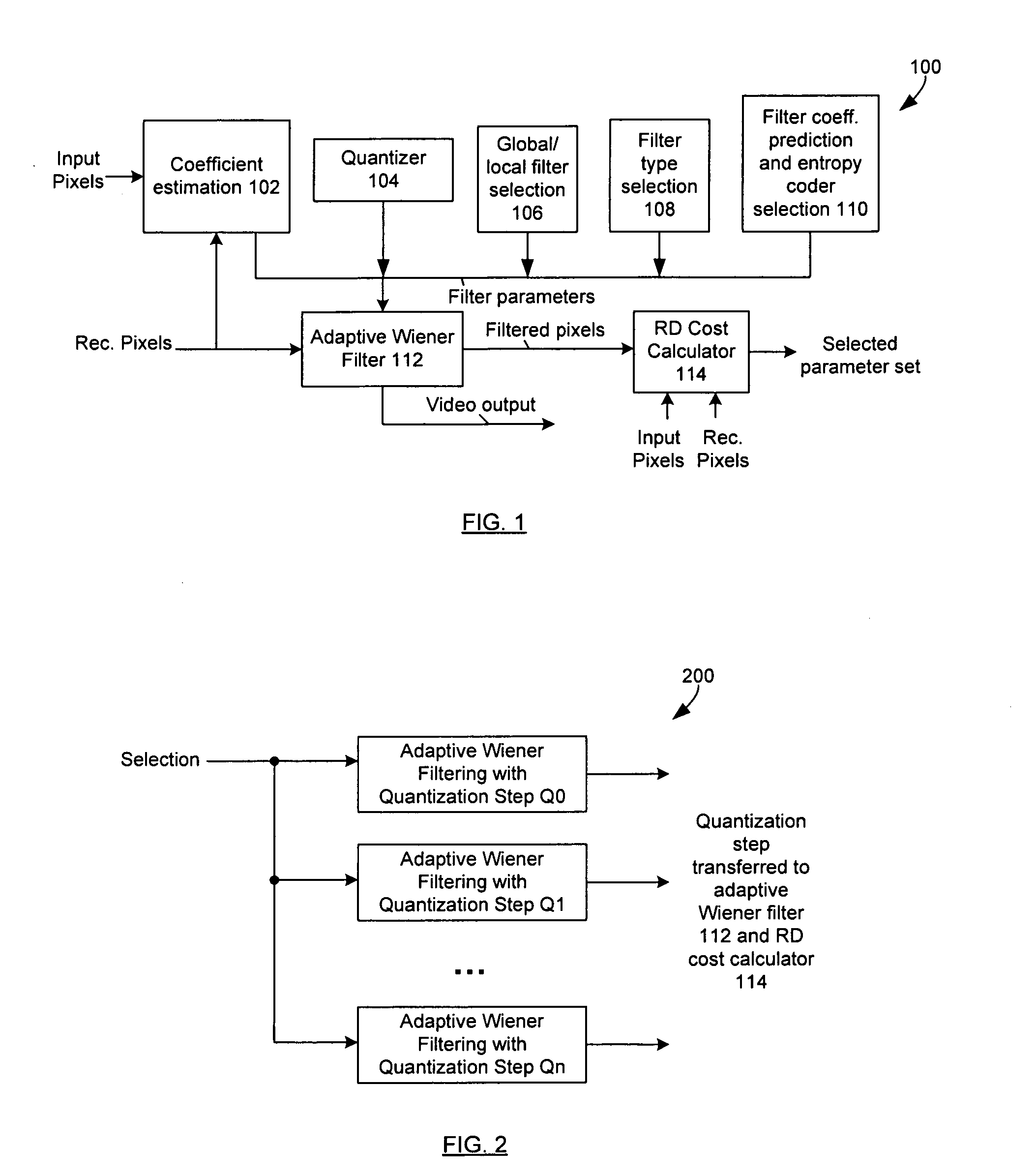
[0014]FIG. 1 depicts an encoder system 100, in accordance with an embodiment of the present invention. Encoder system 100 includes coefficient estimation logic 102, quantizer 104, global / local filter selection 106, filter type selection logic 108, filter coefficient prediction and entropy coder selection logic 110, adaptive wiener filter 112, and RD cost calculator 114. In one embodiment, input pixels and reconstructed pixels (“rec. pixels”) fr...


PUM


Abstract

Techniques are described that can be used to determine parameters of an adaptive Wiener filter to apply to a video region. The following parameters of the Wiener filter may be adjusted: coefficients, coefficient quantization, filter type, filter size, prediction mode, entropy encoding, and number of filter tables. The parameters associated with the lowest rate distortion cost of the encoder are selected for transmission with the encoded video. If not using adaptive Wiener filtering results in a lowest rate distortion cost, then adaptive Wiener filtering is not used for the video region. If using adaptive Wiener filtering results in a lowest rate distortion cost, then the parameters applied by the adaptive Wiener filtering that result in the lowest rate distortion cost are communicated with the filtered video region.

Description

FIELD[0001]The subject matter disclosed herein relates to generally to video encoders and decoders.RELATED ART[0002]A video encoder compresses video information so that more information can be sent over a given bandwidth. The compressed signal may then be transmitted to a receiver that decodes or decompresses the signal prior to display.[0003]Conventional video encoding algorithms result in losses. That is, in the course of compressing the video information, some information may be lost, resulting in decreased picture quality. Ideally, the video quality is improved to the greatest possible extent and the compression is increased to the greatest possible extent. However, these two goals tend to conflict with one another.BRIEF DESCRIPTION OF THE DRAWINGS[0004]Embodiments of the present invention are illustrated by way of example, and not by way of limitation, in the drawings and in which like reference numerals refer to similar elements.[0005]FIG. 1 depicts an example encoder system i...

Claims


Application Information

Patent Timeline
Patent Type & Authority Applications(United States)
IPC IPC(8): H04B1/66
CPCH04N19/147H04N19/46H04N19/82H04N19/117H04N19/17H04N19/61H04N19/80
Inventor XU, LIDONGCHIU, YI-JEN
Owner INTEL CORP
Why Eureka
Try Eureka