
Ribbon band

a technology of ribbon bands and bands, applied in the field of ribbon bands, can solve the problems of monotonous design of ribbon bands, high labor and time requirements of ribbon band fabrication procedures, and less attractive designs, and achieve the effect of improving fabrication efficiency

Inactive Publication Date: 2010-01-14
TSAI YUAN JUNG
View PDF1 Cites 0 Cited by
  • Summary
  • Abstract
  • Description
  • Claims
  • Application Information

AI Technical Summary

Benefits of technology

[0007]The present invention has been accomplished under the circumstances in view. It is one object of the present invention to provide a ribbon band that improves the fabrication efficiency. It is one object of the present invention to provide a ribbon band that can be bent into and kept in any desired shape.

Problems solved by technology

This ribbon band fabrication procedure requires much labor and time.
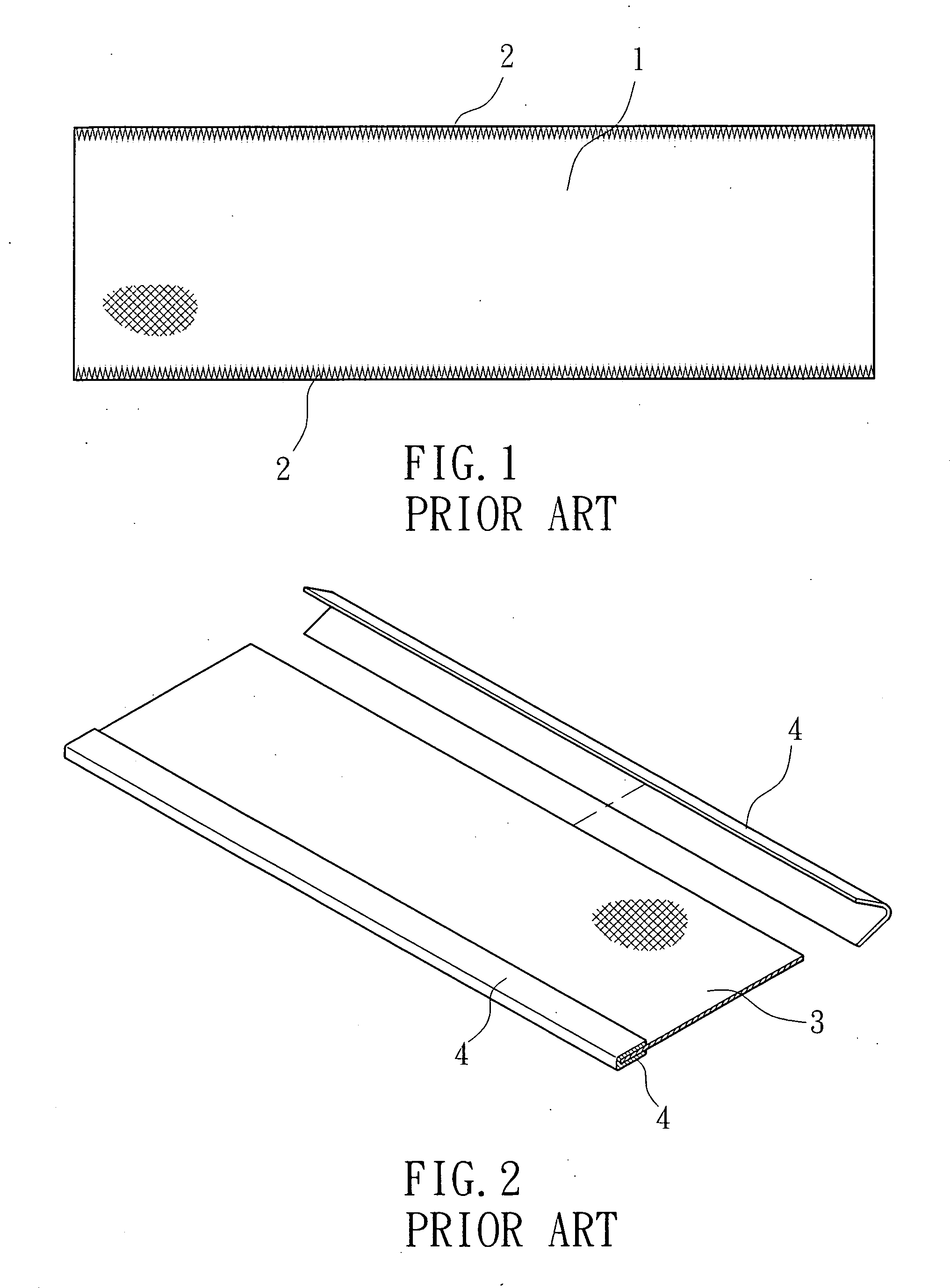
Further, this planar sealing shows no variation in pattern, i.e., this design of ribbon band is monotonous and less attractive.

Method used


Image

  • Ribbon band
  • Ribbon band
  • Ribbon band

Examples


Embodiment Construction

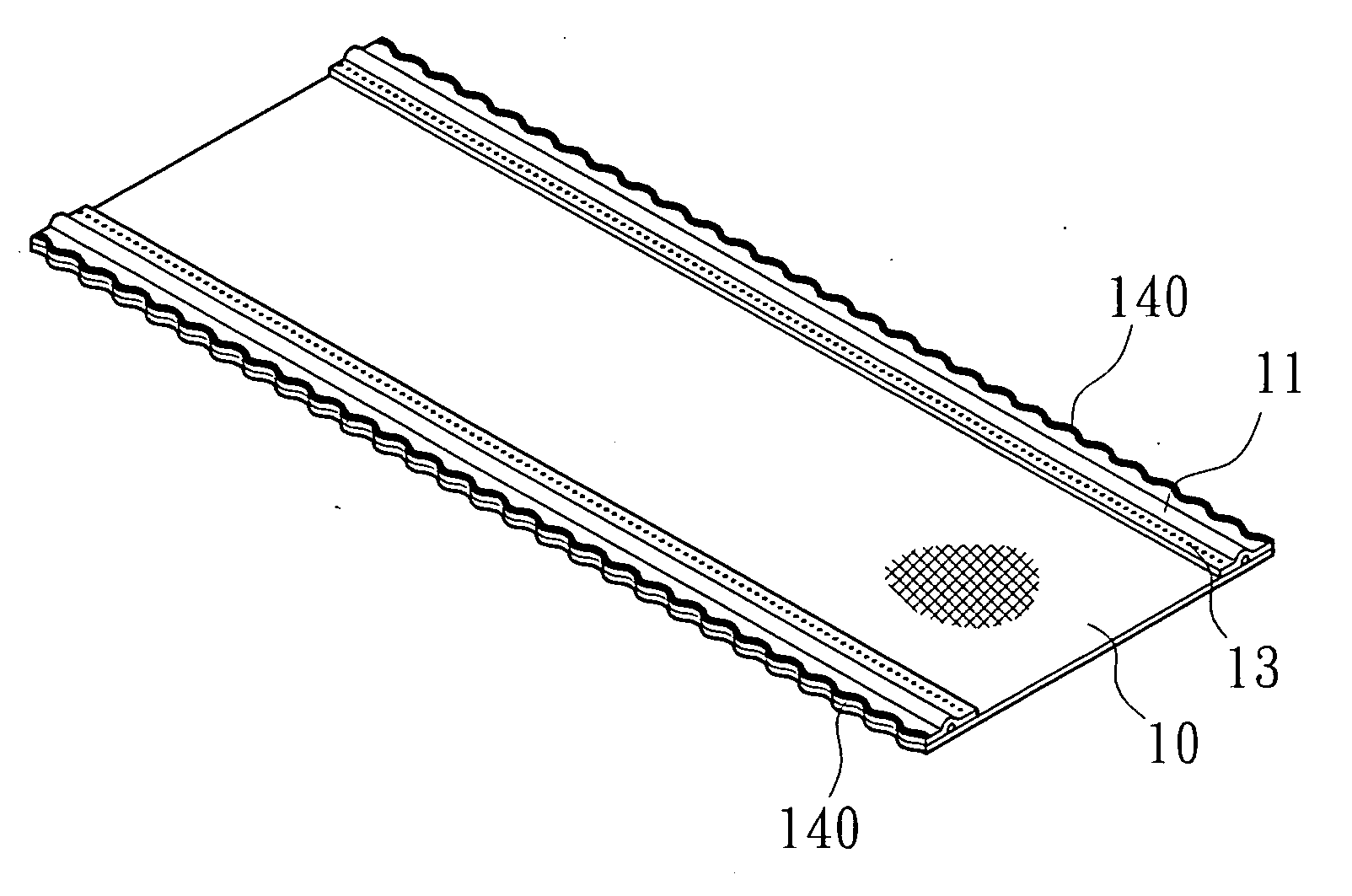
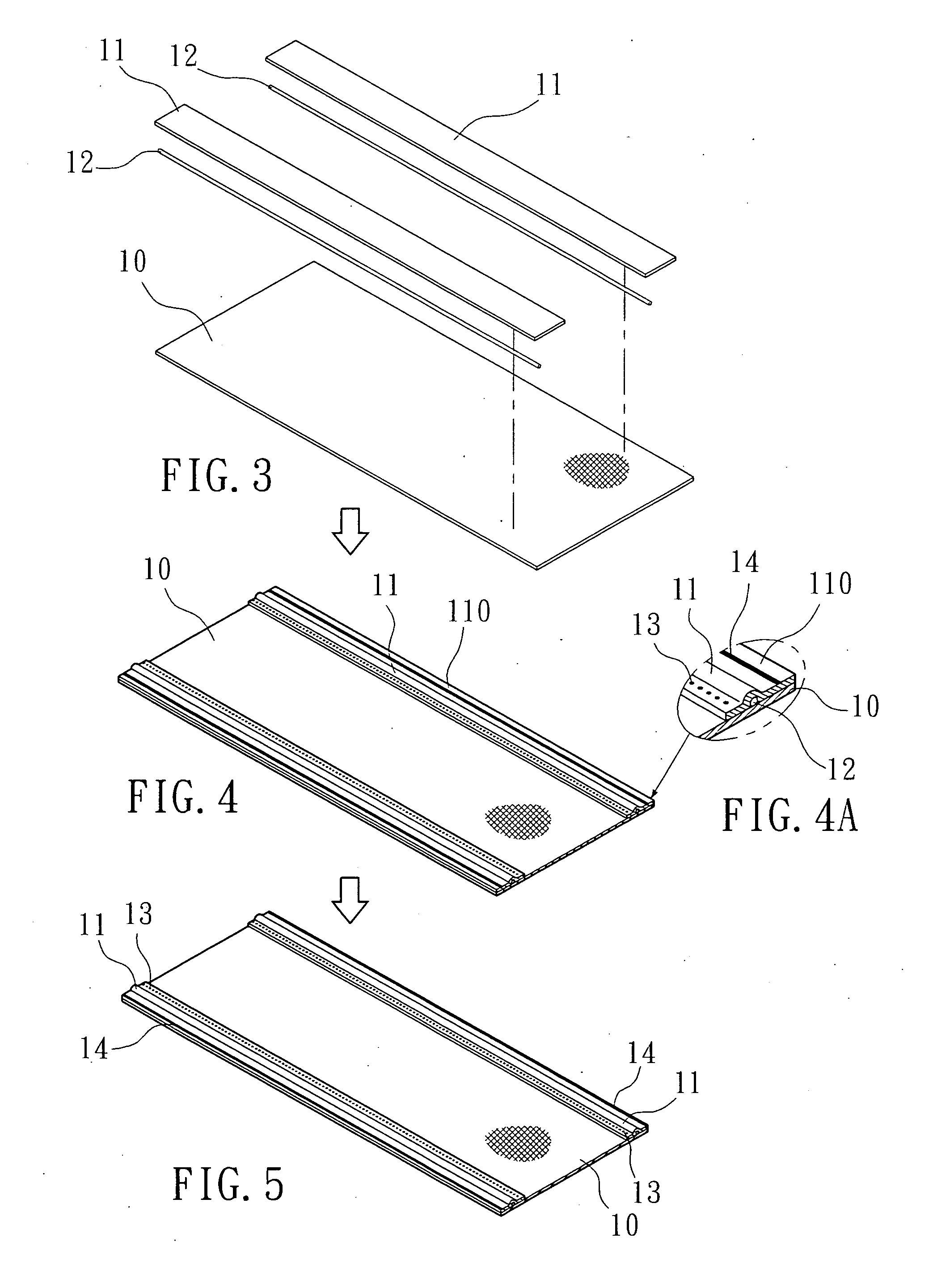
[0018]Referring to FIGS. 3˜6, a ribbon band in accordance with the present invention is shown comprising a narrow elongated base band 10, two trim strips 11 bonded to one side of the base band 10 by means of thermal fusion and respectively extending along two opposite lateral sides of the base band 10, and two metal wires 12 respectively embedded between the base band 10 and the trim strips 11.

[0019]During fabrication, the base band 10 is put in a heat sealing apparatus, and then the metal wires 12 are placed on the top surface of the base band 10 and extended in longitudinal direction in a parallel manner near the two opposite lateral sides of the base band 10, and then the two trim strips 11 are respectively covered on the base band 10 over the metal wires 12, and then the top and bottom heat-sealing wheels of the heat sealing apparatus are respectively rotated over the base band 10 and the trim strips 11, forming a line of weld seal 14 and a line of weld spots 13 at two sides rel...


PUM

PropertyMeasurementUnit
shapeaaaaaaaaaa
timeaaaaaaaaaa
fusion timeaaaaaaaaaa

Abstract

A ribbon band includes a base band and two trim strips respectively bonded to two opposite lateral sides of the base band with an outer line of weld seal and an inner line of weld spots, and two metal wires embedded between the base band and the trim strips.

Description

BACKGROUND OF THE INVENTION[0001]1. Field of the Invention[0002]The present invention relates to ribbon bands and more particularly, to such a ribbon band that can be bent into and kept in any desired shape.[0003]2. Description of the Related Art[0004]Regular ribbon bands are commonly made of chemical fibers by weaving. During the fabrication of a ribbon band, the two opposite rough edges of the ribbon band are fastened with trim strips to prevent unraveling.[0005]FIG. 1 shows a ribbon band according to the prior art. According to this design, the two opposite lateral sides of the base band 1 are covered with zigzag stitches 2 to prevent unraveling. This ribbon band fabrication procedure requires much labor and time.[0006]FIG. 2 shows another structure of ribbon band according to the prior art. According to this design, two trim strips 4 are folded up and respectively covered on the two opposite lateral sides of the base band 3 and then sealed thereto by means of thermal fusion. The...

Claims


Application Information

Patent Timeline
Patent Type & Authority Applications(United States)
IPC IPC(8): B32B15/00
CPCY10T428/24777D04D9/04
Inventor TSAI, YUAN-JUNG
Owner TSAI YUAN JUNG
Learn More