
Disk brake

a technology of brakes and discs, applied in the direction of fluid-actuated brakes, mechanical devices, slack adjusters, etc., can solve the problem that pistons cannot be integrated into cylinders, and achieve the effect of lowering the manufacturing efficiency

Active Publication Date: 2012-10-16
HITACHI ASTEMO LTD
View PDF5 Cites 0 Cited by
  • Summary
  • Abstract
  • Description
  • Claims
  • Application Information

AI Technical Summary

Benefits of technology

The present invention aims to improve the fabrication efficiency of a disk brake by preventing the release of the fitting for anti-rotation locking between the transmission member and the cylinder due to air pressure in the cam chamber. This is achieved by fitting an anti-rotation locking portion formed on the transmission member into a fitting area provided on the cylinder side before a sealing member of the transmission member is located inside the hole. This results in a more secure fitting and prevents the phase shift between the transmission member and the cylinder, allowing for the incorporation of other members without lowering fabrication efficiency.

Problems solved by technology

Consequently, in some cases, a member such as a piston cannot be incorporated into the cylinder.

Method used


Image

  • Disk brake
  • Disk brake
  • Disk brake

Examples


Embodiment Construction

[0016]Hereinafter, an embodiment according to the present invention is described below referring to the drawings.

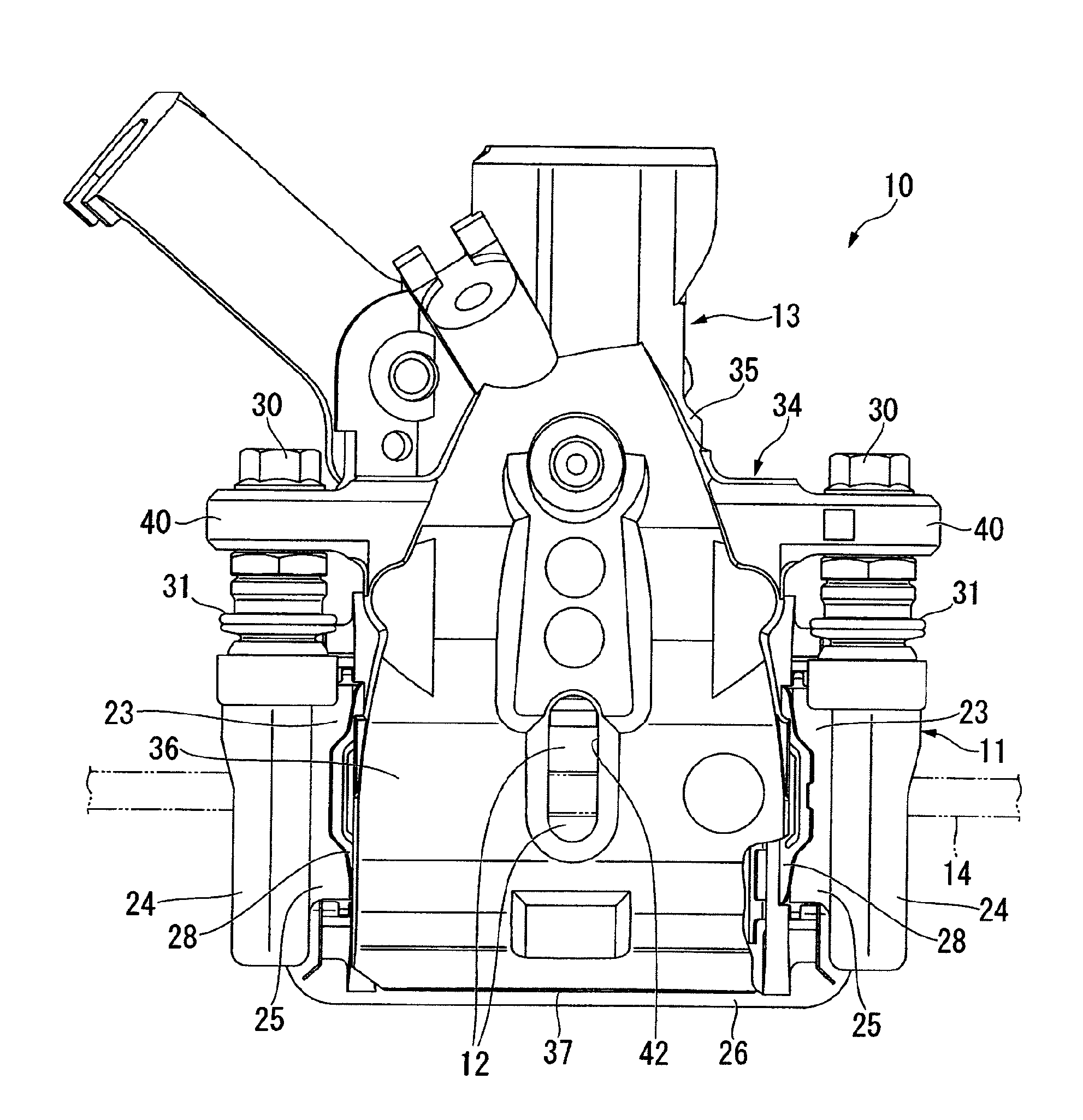
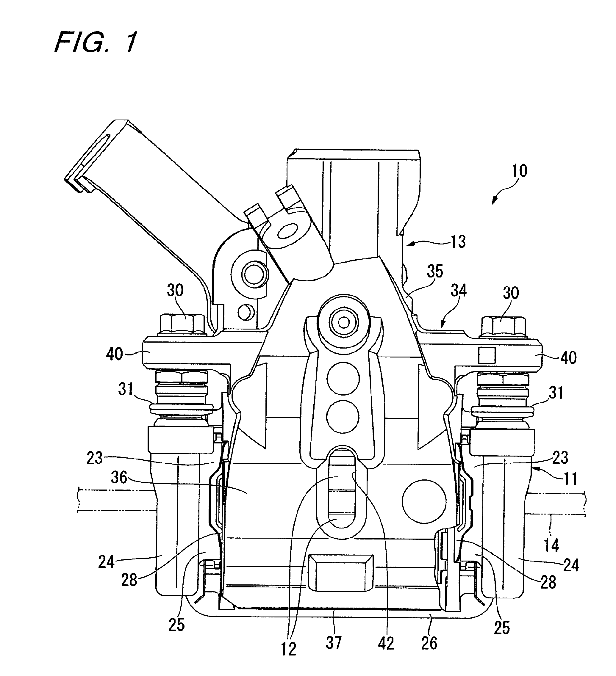
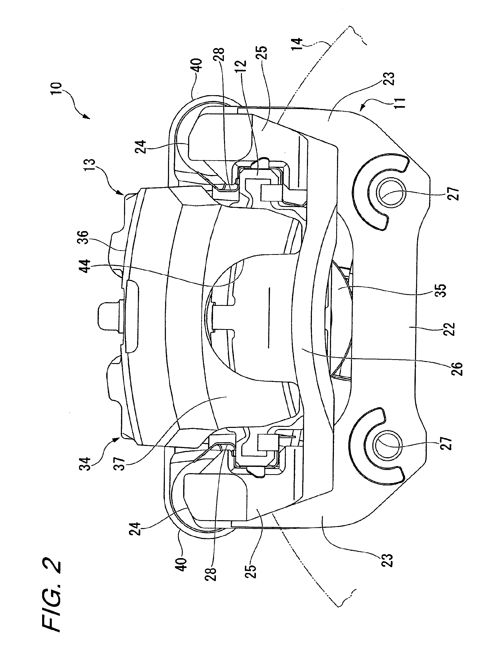
[0017]As illustrated in FIG. 1, a disk brake 10 of this embodiment includes a carrier 11, a pair of pads 12, and a caliper 13. As illustrated in FIG. 2, the carrier 11 is provided so as to pass over the outer diameter side of a disk 14 rotating with a wheel (rotary body) (not shown), which corresponds to a target to be braked, and is fixed to a non-rotating portion of a vehicle (not shown). The pair of pads 12 are supported by the carrier 11 so as to be slidable in an axial direction of the disk 14 while being provided so as to be opposed to both surfaces of the disk 14, respectively. The caliper 13 is supported by the carrier 11 so as to be slidable in the axial direction of the disk 14 while passing over the outer diameter side of the disk 14, and presses the pads 12 against the disk 14, to thereby apply a frictional resistance to the disk 14. Hereinafter, a radial dire...


PUM


Abstract

A disk brake capable of improving fabrication efficiency and having a transmission member. The transmission member (101) includes: an anti-rotation locking portion (130) formed on an outer circumferential portion of the transmission member, the anti-rotation locking portion being slidably fitted into a fitting area (72) on a cylinder (35) side so as to restrict rotation relative to the cylinder; and a seal groove (109) formed in an inserted portion (105). The seal groove stores a sealing member (118) for defining an internal space in the cylinder (35) and a cam chamber (62). The anti-rotation locking portion is fitted into the fitting area (72) on the cylinder side before the sealing member is positioned inside a hole (59) when the inserted portion (105) of the transmission member (101) is inserted into the hole.

Description

BACKGROUND OF THE INVENTION[0001]The present invention relates to a disk brake.[0002]There is known a disk brake with a parking brake, in which a transmission member is pressed by a cam mechanism to thrust a piston (for example, see Japanese Patent Application Laid-open No. 2004-286202).SUMMARY OF THE INVENTION[0003]In a structure in which a transmission member is locked against rotation relative to a cylinder, if a cam chamber which houses a cam mechanism therein is sealed with a seal provided to the transmission member at the time of incorporation of the transmission member into the cylinder, the fitting for anti-rotation locking between the transmission member and the cylinder is sometimes released by return of the transmission member to a cylinder opening side due to an air pressure in the cam chamber even though the transmission member is temporarily pressed in. As a result of the release of the fitting, a phase shift occurs between the transmission member and the cylinder. Con...

Claims


Application Information

Patent Timeline
Patent Type & Authority Patents(United States)
IPC IPC(8): F16D65/56
CPCF16D65/18F16D65/567F16D2121/02F16D2121/14F16D2123/00F16D2125/26
Inventor MIURA, YORIHITONAKAYAMA, SHINICHIHAYASHI, SHIGERUTAKAHASHI, KATSUHIRO
Owner HITACHI ASTEMO LTD
Learn More