
Ceiling Fan Controller Using a Dip Switch to Set Rotation Speed Thereof

a technology of fan controller and dip switch, which is applied in the direction of pump control, non-positive displacement fluid engine, climate sustainability, etc., can solve the problems of complex material management problems, lower efficiency of conventional induction motor, and inability to adjust to an appropriate power output, etc., to increase fabrication efficiency and simplify material management

Inactive Publication Date: 2012-10-04
YAO CHAO CHIN
View PDF7 Cites 0 Cited by
  • Summary
  • Abstract
  • Description
  • Claims
  • Application Information

AI Technical Summary

Benefits of technology

[0007]An objective of the invention is to solve the above-mentioned problems by providing a ceiling fan controller using a DIP switch to set the rotation speed. The ceiling fan controller can adjust to appropriate output power according to the load, so that the DC non carbon brush motor can drive the fan appropriately. That is, only a single controller is needed for ceiling fans of different loads. This reduces complicated problems related to manufacturing different controllers. Production of a single specification simplifies material management, thereby increasing the fabrication efficiency.
[0008]Another objective of the invention is to provide a ceiling fan controller using a DIP switch to set the rotation speed. It can accurately calculate the rotation speed difference when the ceiling fan switches between two rotation speeds.

Problems solved by technology

Such conventional induction motors have lower efficiency.
When the ceiling fan is mounted with different weights of load, the motor cannot adjust to an appropriate power output according to the load.
This will inevitably result in complicated material management problems.
The manufacturing process of ceiling fans cannot be further improved.

Method used


Image

  • Ceiling Fan Controller Using a Dip Switch to Set Rotation Speed Thereof
  • Ceiling Fan Controller Using a Dip Switch to Set Rotation Speed Thereof
  • Ceiling Fan Controller Using a Dip Switch to Set Rotation Speed Thereof

Examples


Embodiment Construction

[0014]The present invention will be apparent from the following detailed description, which proceeds with reference to the accompanying drawings, wherein the same references relate to the same elements.

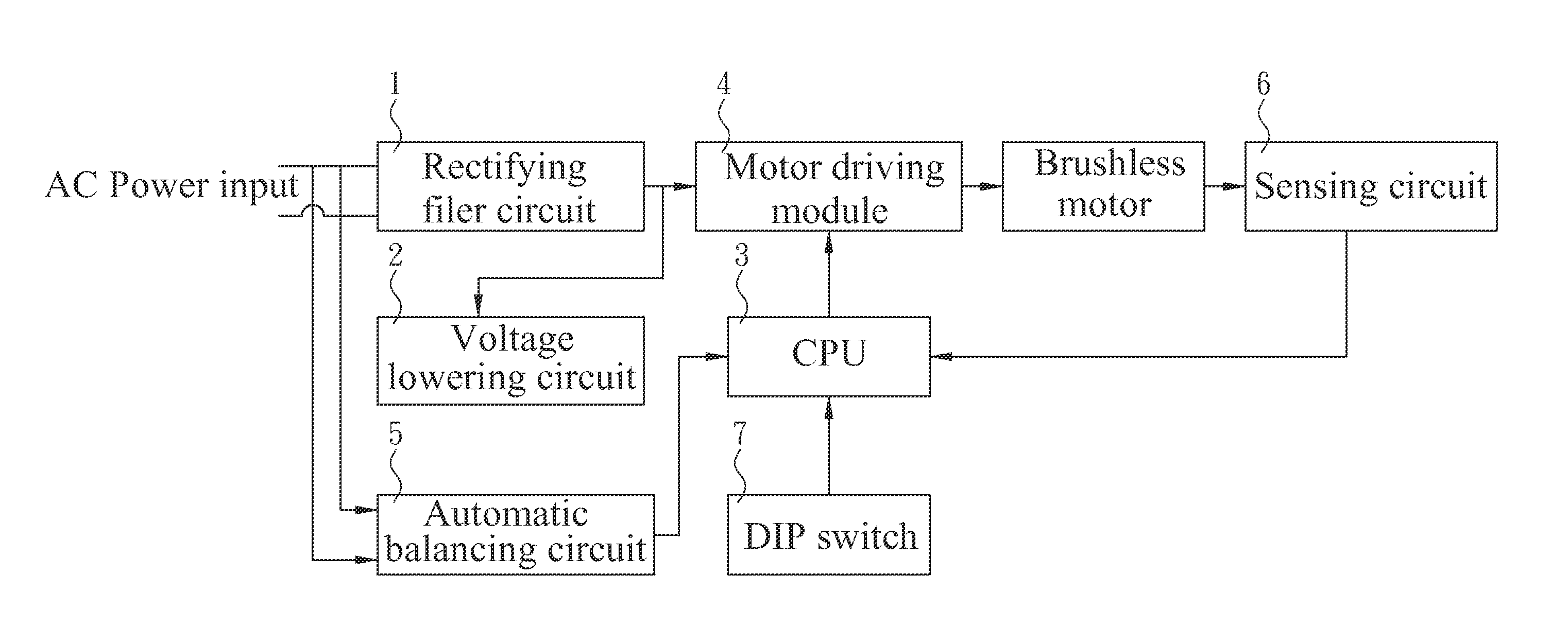
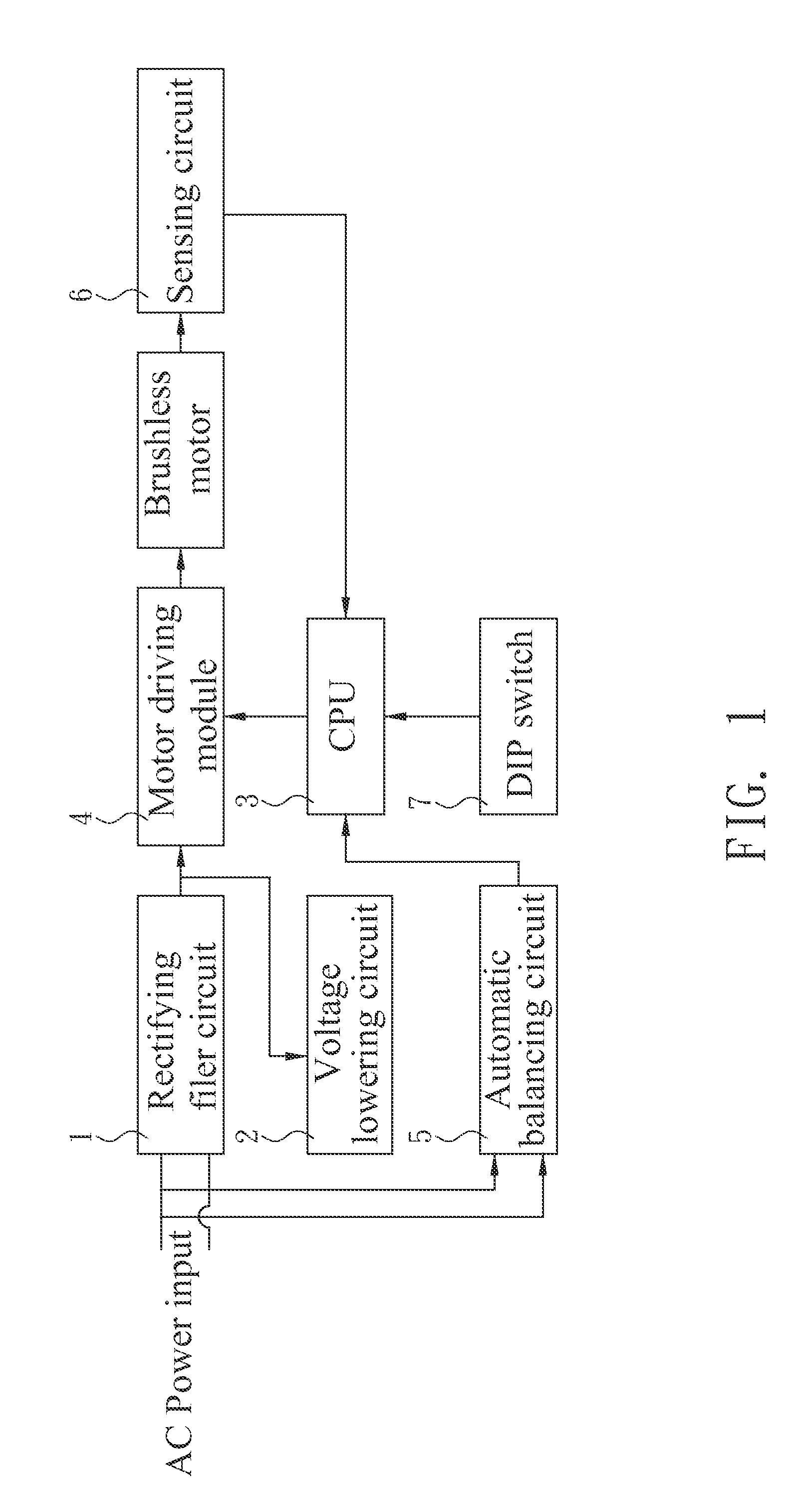
[0015]The preferred embodiment of the ceiling fan controller using a DIP switch to set a rotation speed is shown in FIG. 1. The controller in this embodiment includes: a rectifying filter circuit 1, a central processing unit (CPU) 3, a motor driving circuit 4, an automatic balancing circuit 5, and a sensing circuit 6.

[0016]The rectifying filter circuit 1 rectifies and filters AC power into DC power to provide the power for driving the DC non carbon brush motor. In this embodiment, the rectifying filter circuit 1 electrically connects to a voltage lowering circuit 2 to provide the power required by the system.

[0017]The CPU 3 is built in with a control routine to process input / output signals of the controller. The motor driving module 4 drives the DC non carbon brush motor of the ceilin...


PUM


Abstract

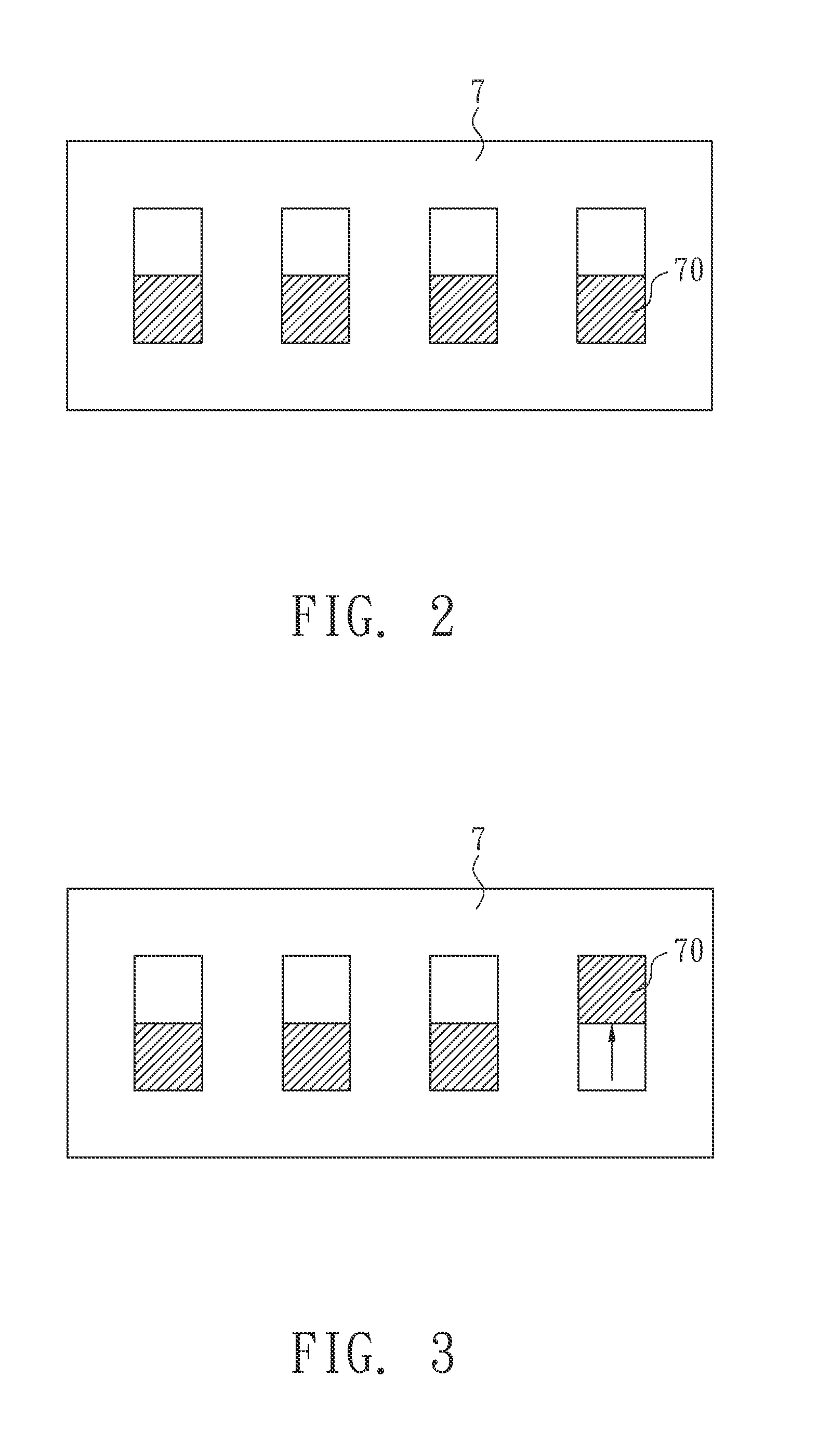
A ceiling fan controller using a DIP switch to set a rotation speed comprises a rectifying filter circuit, a CPU, a motor driving module, a voltage lowering circuit, an automatic balancing circuit, and a sensing circuit for a DC non carbon brush motor. A DIP switch electrically connects to the CPU to set different maximum rotation speeds for the DC non carbon brush motor.

Description

BACKGROUND OF THE INVENTION[0001]1. Field of Invention[0002]The invention relates to a ceiling fan controller and, in particular, to a controller that uses a DIP switch to control the fan rotation speed.[0003]2. Related Art[0004]The motors used to drive ceiling fans in the prior art are induction motors. Such conventional induction motors have lower efficiency. Therefore, most ceiling fans use DC non carbon brush motors nowadays. A controller is employed to control the rotation speed of the DC non carbon brush motor.[0005]Since there are various kinds of loads on the ceiling fans, the maximum output power of the DC non carbon brush motor is fixed if the maximum rotation speed thereof is fixed. When the ceiling fan is mounted with different weights of load, the motor cannot adjust to an appropriate power output according to the load. For example, suppose the actual load of a ceiling fan is larger than the default one. When the DC non carbon brush motor is still driven according to th...

Claims


Application Information

Patent Timeline
Patent Type & Authority Applications(United States)
IPC IPC(8): F04B49/06
CPCF04D27/004F04D25/088Y02B30/70
Inventor LIN, KUO TSUN
Owner YAO CHAO CHIN
Learn More