Liquid manipulation device

a technology of manipulating device and liquid, which is applied in the direction of fixed microstructural device, laboratory glassware, instruments, etc., can solve the problems of difficulty in appropriately adjusting such environmental conditions, low control capability of manipulating device droplets, and hindering widespread application of ewod, etc., to improve fabrication efficiency and enhance the ability to control liquid

Pending Publication Date: 2022-01-06
NAT INST OF ADVANCED IND SCI & TECH
View PDF0 Cites 0 Cited by
  • Summary
  • Abstract
  • Description
  • Claims
  • Application Information

AI Technical Summary

Benefits of technology

[0017]A liquid manipulation device according to an aspect can have an enhanced capability to control liquid, in particular, droplets, and offer improved fabrication efficiency.

Problems solved by technology

However, it is difficult to appropriately adjust such environmental conditions, and the liquid manipulation devices have low capabilities to control droplets.
This is a factor that hinders widespread application of EWOD.

Method used


Image

  • Liquid manipulation device
  • Liquid manipulation device
  • Liquid manipulation device

Examples


first embodiment

[0025]A liquid manipulation device according to a First Embodiment is described below.

“Outline of Liquid Manipulation Device”

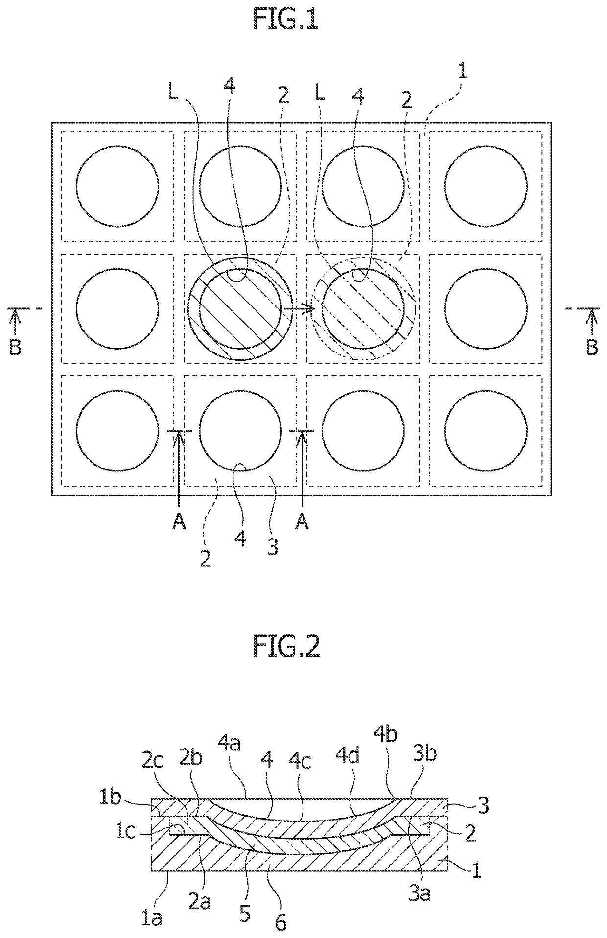
[0026]The liquid manipulation device according to the present Embodiment is described in outline with reference to FIGS. 1 and 2. The liquid manipulation device includes a substrate 1 having a sheet shape or a film shape so as to have flexibility. The substrate 1 has a back surface 1a, and a front surface 1b located opposite the back surface 1a with respect to a thickness direction of the substrate 1.

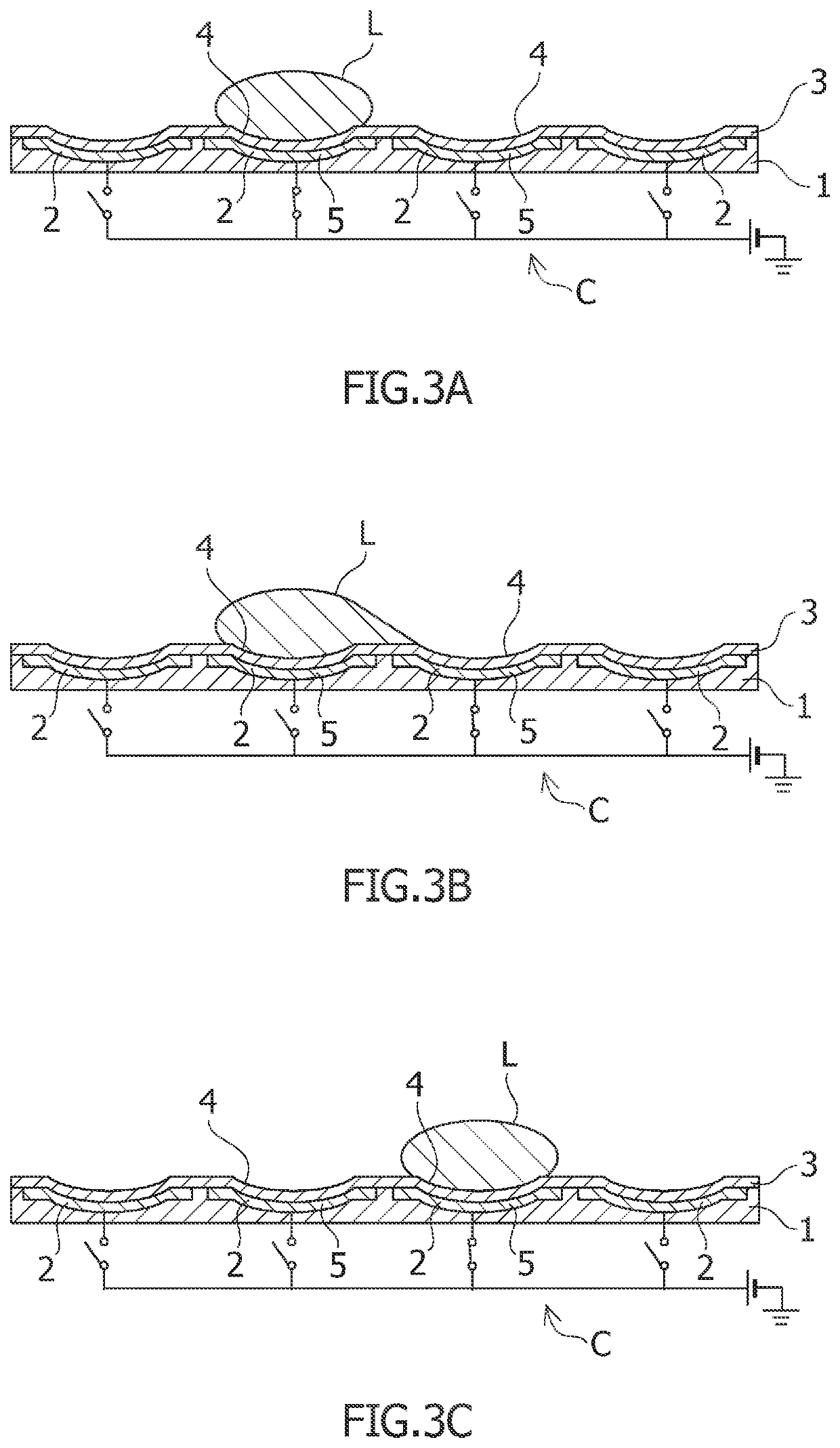
[0027]The liquid manipulation device includes electrodes 2 located on the front surface 1b of the substrate 1. The liquid manipulation device includes an insulating layer 3 located over the front surface 1b of the substrate 1 so as to cover the electrodes 2. The liquid manipulation device is configured to move liquid L, in particular, a droplet L, on a front surface 3b of the insulating layer 3 by using an electrostatic force that is generated when voltage is appl...

second embodiment

[0053]A liquid manipulation device according to a Second Embodiment is described below. The liquid manipulation device according to the present Embodiment is similar to the liquid manipulation device according to the First Embodiment except for the substrate. Constituent elements of the present Embodiment that are similar to those of the First Embodiment, are designated with the same reference signs as those of the First Embodiment.

[0054]As shown in FIG. 5, the liquid manipulation device according to the present Embodiment includes a substrate 11 that is similar to the substrate 1 of the First Embodiment, except for what is described below. The substrate 11 includes a back surface 11a, a front surface 11b, and a concave portion 11c that correspond to the back surface 1a, the front surface 1b, and the concave portion 1c of the substrate 1 of the First Embodiment, respectively. The substrate 11 includes second dimple-corresponding portions 16 that correspond to the second dimple-corre...


PUM

PropertyMeasurementUnit
thicknessaaaaaaaaaa
thicknessaaaaaaaaaa
flexibilityaaaaaaaaaa

Abstract

A liquid manipulation device has an enhanced ability to control liquid, in particular, a droplet, and offers improved fabrication efficiency. The liquid manipulation device according to the present invention includes: a substrate 1, 11 including a sheet shape or a film shape to have flexibility; a plurality of electrodes 2 located on a front surface 1b, 11b of the substrate 1, 11; and an insulating layer located over the front surface 1b, 11b of the substrate 1, 11 to cover the electrodes 2. The liquid manipulation device is configured to move liquid L on a front surface 3b of the insulating layer 3 by using an electrostatic force that is generated when voltage is applied to at least one of the electrodes 2. In the liquid manipulation device, the insulating layer 3 includes dimples 4 that are located in correspondence with the electrodes 2 and are curved concave in a concave direction directed from the front surface 3b of the insulating layer 3 toward the back surface 3a of the insulating layer 3. Each of the electrodes 2 includes a dimple-corresponding portion 5 being curved concave in the concave direction together with one of the dimples 4 that is located in correspondence with the corresponding electrode 2.

Description

TECHNICAL FIELD[0001]The present invention relates to a liquid manipulation device configured to move liquid using electrostatic force.BACKGROUND ART[0002]Various technological fields, such as biotechnology, medicine, drug development, microelectromechanical systems (MEMS), and / or the like are focusing increasing attention on EWOD (Electro Wetting On Dielectric). Based on EWOD, liquids, in particular, droplets, are manipulated using electrostatic force. In particular, in the technological fields of biotechnology, medicine, drug development, and / or the like, EWOD has a great potential for handling rare reagents, dangerous agents, and / or the like.[0003]Typically, a device based on EWOD (hereinafter referred to as “liquid manipulation device”) includes: a substrate having electrodes; and an insulating layer having a back surface and a front surface. The back surface of the insulating layer is located on and bonded to a front surface of the substrate. The front surface of the insulating...

Claims


Application Information

Patent Timeline
Patent Type & Authority Applications(United States)
IPC IPC(8): B01L3/00G01N35/08B01J19/08
CPCB01L3/502G01N35/08B01L2400/0427B01J2219/0815B01J19/088B01L3/502792B01L3/50273B01L2400/0433B01L2200/0621B01L2300/0816B01L2300/0829B01L2300/0645B01L2300/0887B01L2300/123B01L2300/161B01L2400/0415B01L2300/0851B01J19/08B81B1/00G01N37/00
Inventor MOGI, KATSUOADACHI, SHUNGOINOUE, TOMOYANATSUME, TOHRU
Owner NAT INST OF ADVANCED IND SCI & TECH
Why Eureka
Try Eureka