
Vehicle control device

Active Publication Date: 2010-01-14
DENSO CORP +1
View PDF0 Cites 18 Cited by
  • Summary
  • Abstract
  • Description
  • Claims
  • Application Information

AI Technical Summary

Benefits of technology

[0027]It is an object of the present invention to provide an improved vehicle control device capable of decreasing a response delay between an actual acceleration and a target acceleration.
[0033]That is, according to the vehicle control device according to the present invention, it is possible to decrease the time length to affect the brake torque generated by the brake mechanism to the driver's vehicle, in other words, the vehicle control device according to the present invention can decreases the time interval to apply the brake power generated by the brake mechanism to the driver's vehicle, when compared with the conventional vehicle control devices in which the brake torque generated by the brake mechanism is 0 [N·m] immediately after the brake limitation control is switched to the brake use control.
[0034]Therefore, according to the vehicle control device of the present invention, it is possible to decrease the response delay of the actual acceleration to the target acceleration (namely, to increase the actual acceleration of the driver's vehicle to follow the target acceleration). As a result, the vehicle equipped with the vehicle control device according to the present invention can provide driving comfort to the vehicle driver and passengers.
[0036]By the way, when the brake mechanism generates some amount of the brake torque immediately after the brake limitation control is switched to the brake use control, it is possible to reliably decrease the time length necessary for the transmission of the brake power by the brake mechanism to the driver's vehicle. It is further possible to smoothly switch the brake torque generated by the power train mechanism to the brake torque generated by the brake mechanism.

Problems solved by technology

Such a conventional vehicle control device has a drawback.
That is, the conventional vehicle control device has the problem to cause a time delay until the driver's vehicle completely reaches the target acceleration (deceleration) because a constant deceleration is applied to the driver's vehicle from the state of brake torque of zero [N·m] until the state of generating an effective brake torque, by the hydraulic brake mechanism, to generate the effective acceleration (or deceleration) for the driver's vehicle.
Thus, the conventional vehicle control device often inconveniences the vehicle driver and passengers by the response delay of the actual acceleration of the vehicle from the target acceleration.

Method used


Image

  • Vehicle control device
  • Vehicle control device
  • Vehicle control device

Examples


embodiment

Relationship Between Claims and Embodiment

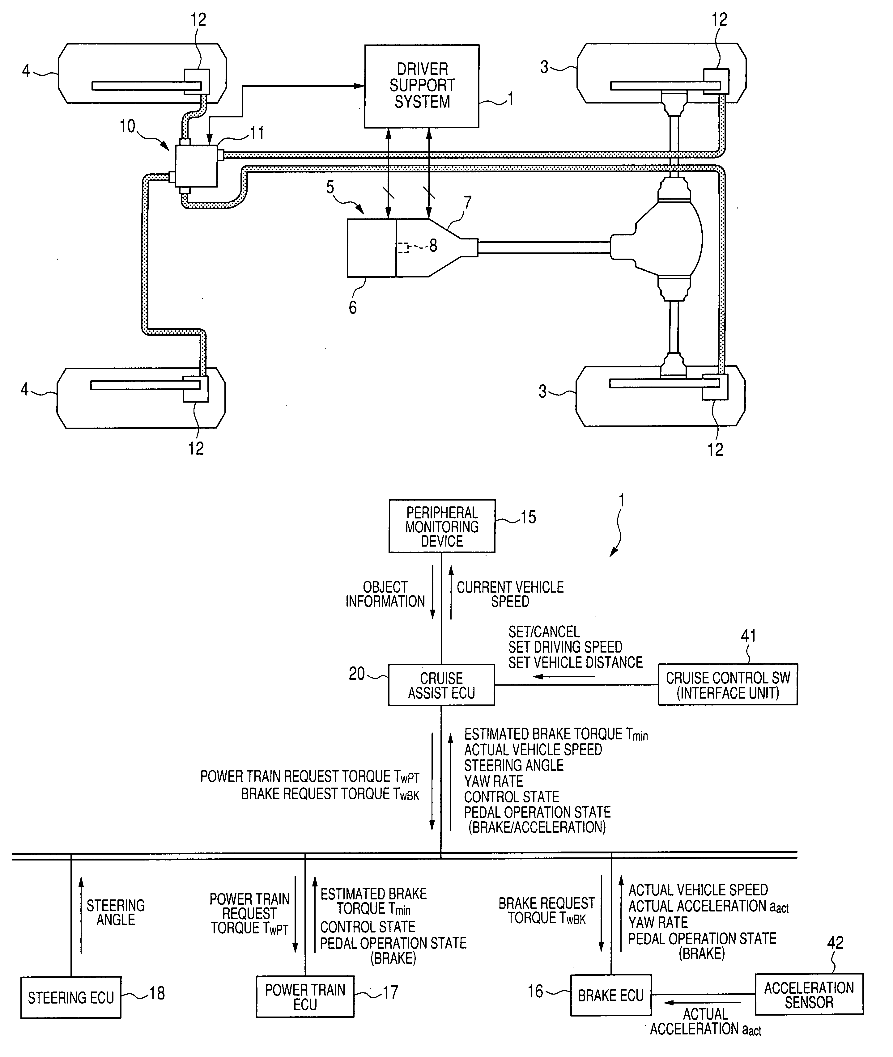
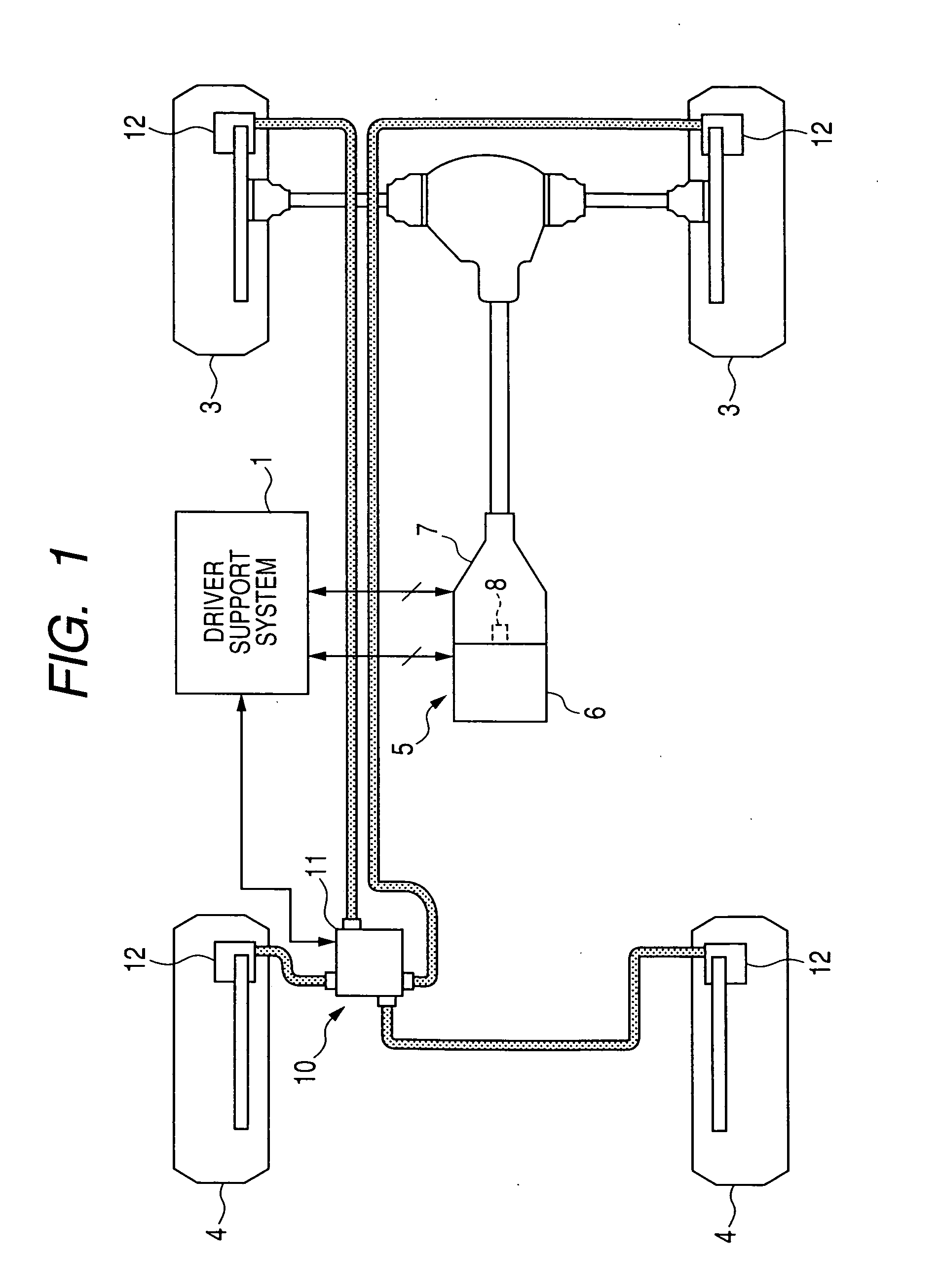
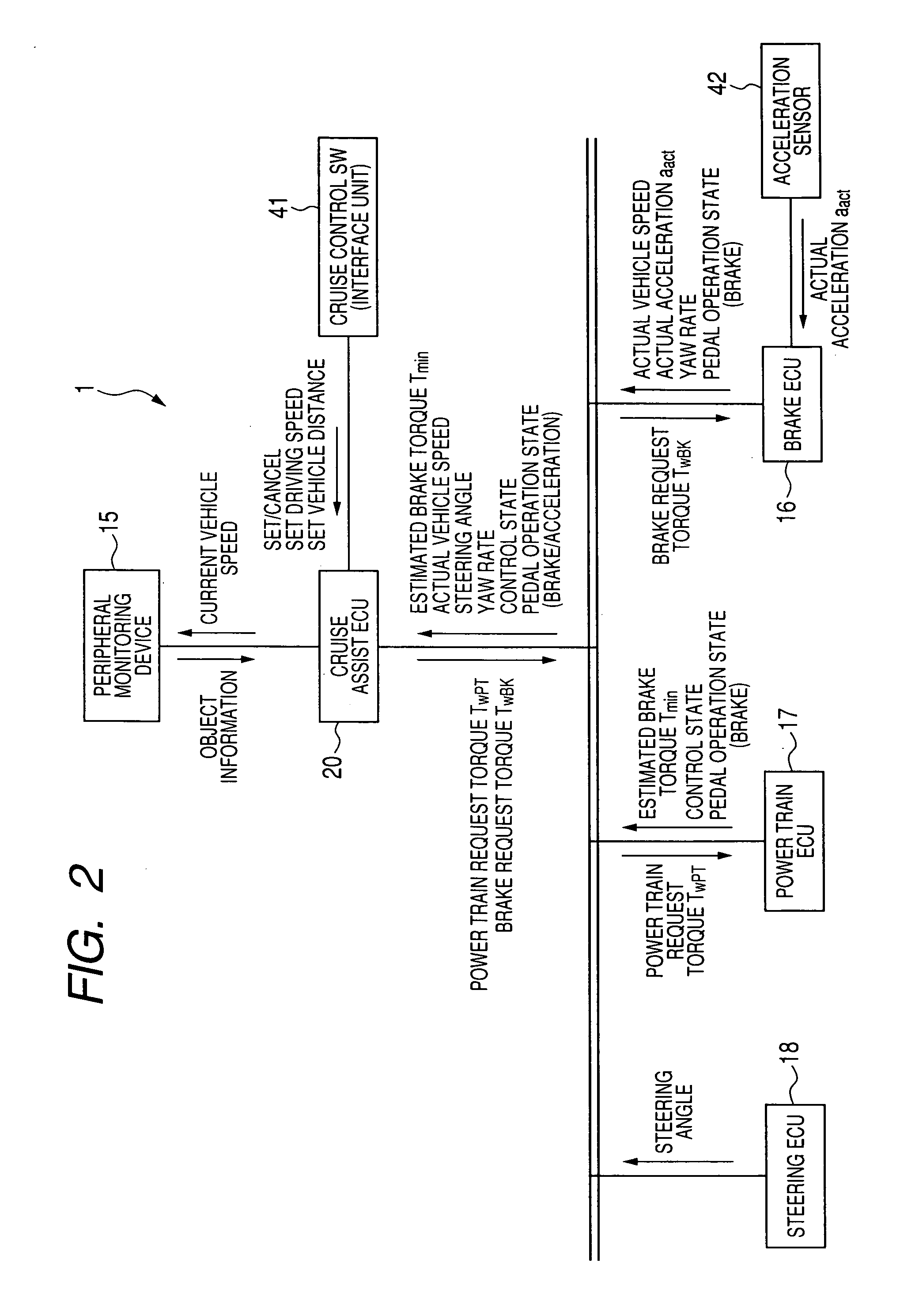
[0195]The target acceleration calculating unit 21 corresponds to a target value calculation means. The function for the cruise assist ECU 20 to obtain an actual acceleration aact from the acceleration sensor 42 corresponds to an acceleration obtaining means.

[0196]The power train deviation calculating unit 28, the power train feedback control unit 29, the power train control amount calculating unit 30, and the feedforward control unit 35 in the acceleration control unit 22 correspond to a power train control means.

[0197]The brake deviation calculation unit 31, the brake feedback control unit 32, the brake control amount calculation unit 33, and the feedforward control unit 35 in the acceleration control unit 22 correspond to a brake control means.

[0198]Further, the feedback amount limitation control unit 38 in the embodiment corresponds to a state detection and switching means.

[0199]The brake feedback control process executed at the brake lim...


PUM


Abstract

In a vehicle control device, a brake feedback control unit calculates a brake feedback torque Tfb-BK using a PID control model when a current state is a brake feedback use state. The brake feedback control unit stops the calculation of the brake feedback torque Tfb-BK when the current state is a brake feedback limitation state, and stores as an output value the brake feedback torque Tfb-BK that is output at a brake limitation start timing. At a brake limitation release timing, the brake feedback control unit restarts the feedback control using the stored brake feedback torque Tfb-BK as an initial value. The brake mechanism can thereby generate a predetermined brake torque of not more than 0 [N·m] immediately after the brake limitation release timing.

Description

CROSS-REFERENCE TO RELATED APPLICATION[0001]This application is related to and claims priority from Japanese Patent Application No. 2008-182804 filed on Jul. 14, 2008, the contents of which are hereby incorporated by reference.BACKGROUND OF THE INVENTION[0002]1. Field of the invention[0003]The present invention relates to a vehicle control device mounted to a vehicle for controlling a vehicle acceleration so that an actual acceleration (or a current acceleration) of the vehicle becomes equal to a target acceleration requested in response to a running state of the vehicle.[0004]2. Description of the Related Art[0005]There have been known various types of driver support systems for cruise control and adaptive cruise control. The cruise control keeps a vehicle speed at a set speed (or a target speed). The adaptive cruise control keeps a distance between a driver's vehicle and a front running vehicle at a predetermined vehicle distance (or a target vehicle distance) that is set in advan...

Claims


Application Information

Patent Timeline
IPC IPC(8): B60W10/10B60T7/12B60W10/00B60W10/04B60W10/06B60W10/08B60W10/18B60W10/184B60W10/188F02D29/00F02D29/02
CPCB60T13/662B60T2201/02B60T2230/04B60W10/06B60W10/10B60W10/184Y10T477/677B60W30/18109B60W2520/105B60W2720/106Y10T477/639Y10T477/688B60W30/16
Inventor UMAKOSHI, MOTOAKIFUKUDA, SHOTAROKUMABE, HAJIMETAKEDA, MASAYOSHIMORI, YUKIO
Owner DENSO CORP
Learn More