
Steerable catheter with distending lumen-actuated curling catheter tip

a catheter tip and actuation technology, applied in the field of catheters, can solve the problems of difficult positioning of the catheter in any particular direction, difficult steering and maneuvering of the catheter in the patient's body, etc., and achieve the effect of facilitating deployment/positioning of the catheter and minimizing the possibility of cell hyperthermia

Inactive Publication Date: 2010-01-14
LAWRENCE LIVERMORE NAT SECURITY LLC
View PDF8 Cites 32 Cited by
  • Summary
  • Abstract
  • Description
  • Claims
  • Application Information

AI Technical Summary

Benefits of technology

[0006]One aspect of the present invention includes a steerable catheter, comprising: an elongated catheter body having proximal and distal ends and a longitudinal axis; and a catheter tip having an elastomeric cylindrical body with a longitudinal axis and coaxially connected to the distal end of the elongated catheter body, and at least one steering lumen each offset from the longitudinal axis of the elastomeric cylindrical body and extending substantially the length thereof so that increasing the internal pressure of the steering lumen curls the longitudinal axis of the elastomeric cylindrical body towards the steering lumen for steering the catheter tip; and means for independently controlling the internal pressure of each steering lumen to control the direction and magnitude of the curl.
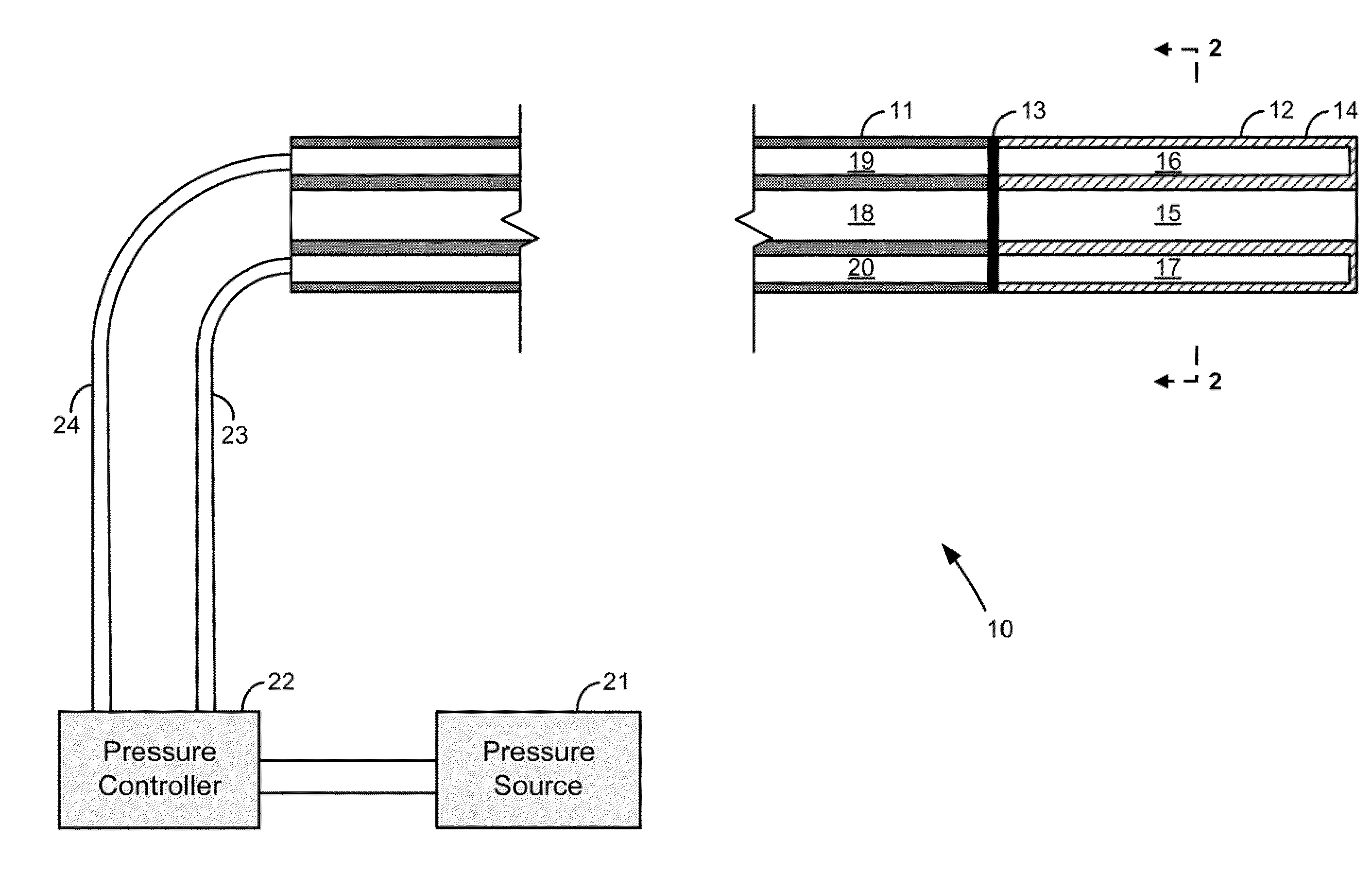
[0008]Generally, the present invention is directed to a steerable catheter having an elastomeric catheter tip connected to an elongated catheter body, with the catheter tip having an elastomeric cylindrical body and one or more steering lumens for curling, i.e. controlling the curvature of, the elastomeric catheter tip by controlling the internal pressures of the steering lumens. In this manner, the catheter tip may be curled in any direction to aid in directing the catheter up an appropriate capillary.
[0009]The basic approach is to extend one or more expandable steering lumens through substantially the length of the elastomeric catheter tip and offset from the longitudinal center axis of the elastomeric catheter tip, so that selectively expanding the steering lumen volumes operates to curl the catheter tip towards the expanded (distended) steering lumen or lumens. Expansion of the steering lumens may be effected at the proximal end either pneumatically (e.g. carbon dioxide) or hydraulically (e.g. saline solution) through an external source, or by phase change expansion of a thermally expandable media (e.g. solid to liquid wax). The amount of force generated in a small volume area using this technique of off-centered volume expansion in an elastomeric catheter tip can be quite high. By careful choice of the morphology of the expandable volume, useful work can be performed at the catheter tip to effect steering and direction control.
[0011]And various types of thermally expandable media may include, for example, silicone which expands about 0.1% / ° C., phase changing polymers which expand about 40% upon melting, or polymers with low boiling points to obtain actuation through gas formation. Actuation temperatures near body temperature can be chosen to minimize the possibility of hyperthermia of the cells. Another example uses laser light to heat the polymer similar to that used in synergistic projects such as those proposed to deploy devices to clear arterial blockages causing strokes.
[0012]The primary application of the directed movement / steering of a catheter provided by the present invention would be for medical catheters to facilitate deployment / positioning of the catheter to the desired internal region of a patient. However, catheter tip steering may also be useful in other non-medical applications, such as for example performing inspections of devices, machines, or systems in hard-to-reach areas.

Problems solved by technology

Despite their many benefits, the steering and maneuvering of catheters in a patient's body can be difficult since catheter control is generally performed from outside the body at a proximal end of the catheter opposite the leading or distal end, and it is often difficult to aim the distal end of the catheter in any particular direction to force the catheter down one capillary versus another, such as when a fork is encountered.

Method used


Image

  • Steerable catheter with distending lumen-actuated curling catheter tip
  • Steerable catheter with distending lumen-actuated curling catheter tip
  • Steerable catheter with distending lumen-actuated curling catheter tip

Examples


Embodiment Construction

[0024]Turning now to the drawings, FIGS. 1-3 show a first exemplary embodiment of the steerable catheter of the present invention, and generally indicated at reference character 10. In particular, FIG. 1 is a schematic cross-sectional view of the steerable catheter, and shown having an elastomeric catheter tip 12 connected to a (preferably semi-rigid) elongated catheter body 11, and a pressurized fluid source 21 for selectively and independently supplying selected steering lumens in the elastomeric catheter tip 12 with pressurized fluid via the elongated catheter body 11.

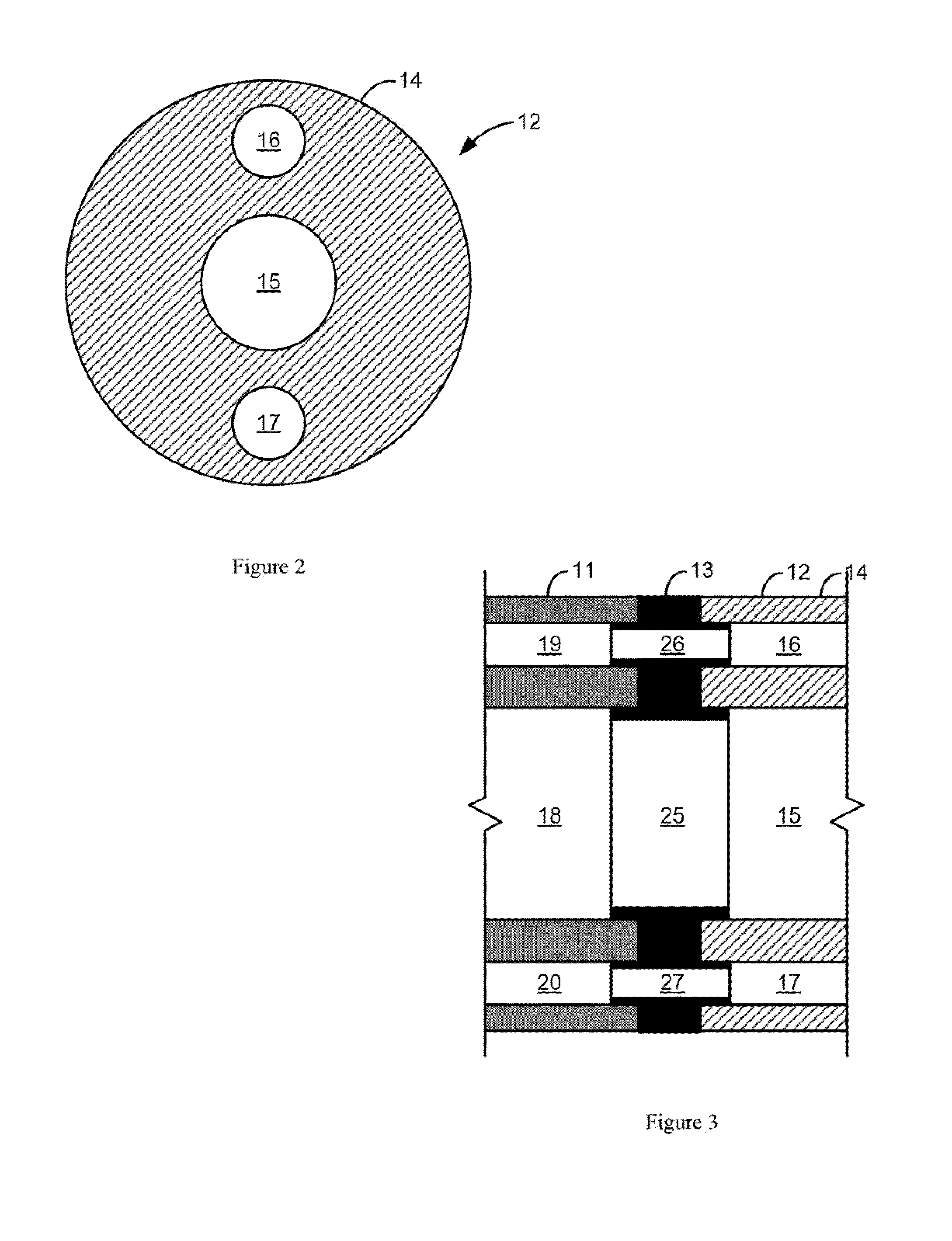
[0025]As can be seen in FIGS. 1 and 2, the elastomeric catheter tip 12 has a generally cylindrical body that is shown in particular as an elastomeric tubular sidewall 14. In the tubular configuration, a central lumen is formed surrounded by the elastomeric tubular sidewall. In either case, the cylindrical body / tubular sidewall 14 has a longitudinal axis along which the length of the cylindrical body / tubular sidewall...


PUM


Abstract

A steerable catheter having a catheter tip connected to an elongated catheter body, with the catheter tip having an elastomeric cylindrical body and one or more steering lumens each offset from the longitudinal axis of the elastomeric cylindrical body and extending substantially the length of the elastomeric cylindrical body so that increasing the internal pressure of one or more of the steering lumens using, for example, a pneumatic or hydraulic pressure source or heating a thermally expandable media in the steering lumens, operates to curl the longitudinal axis of the elastomeric cylindrical body towards the internally pressurized steering lumen or lumens for steering the catheter tip.

Description

CROSS-REFERENCE TO RELATED APPLICATIONS[0001]This application claims priority in provisional application no. 61 / 080164, filed on Jul. 11, 2008, entitled “Pneumatic / Hydraulic Articulating Catheter” by Robin R. Miles et al, incorporated by reference herein.FEDERALLY SPONSORED RESEARCH OR DEVELOPMENT[0002]The United States Government has rights in this invention pursuant to Contract No. DE-AC52-07NA27344 between the United States Department of Energy and Lawrence Livermore National Security, LLC for the operation of Lawrence Livermore National Laboratory.FIELD OF THE INVENTION[0003]The present invention relates to catheters, and more particularly to the steering and directional control of catheters using an elastomeric catheter tip that resiliently curls in response to and in the direction of one or more internally pressurized lumens which extend substantially the length of the elastomeric catheter tip from an offset position relative to the longitudinal axis.BACKGROUND OF THE INVENTIO...

Claims


Application Information

Patent Timeline
Patent Type & Authority Applications(United States)
IPC IPC(8): A61M25/092
CPCA61M25/0158A61M25/0155
Inventor MILES, ROBIN R.SCHUMANN, DANIEL L.PEARSON, MARK A.HILKEN, DAWN
Owner LAWRENCE LIVERMORE NAT SECURITY LLC
Learn More