Piezoelectric sensor, a method for manufacturing a piezoelectric sensor and a medical implantable lead comprising such a piezoelectric sensor

a piezoelectric sensor and manufacturing method technology, applied in the manufacture/assembly of the piezoelectric/electrostrictive device, catheters, external electrodes, etc., can solve the problems of difficult contact of the piezoelectric material and the piezoelectric sensor, and achieve the effect of increasing the sensitivity of the sensor

Inactive Publication Date: 2010-01-14
ST JUDE MEDICAL
View PDF10 Cites 18 Cited by
  • Summary
  • Abstract
  • Description
  • Claims
  • Application Information

AI Technical Summary

Benefits of technology

[0014]The invention is based on the insight that the above objects may be achieved by arranging the piezoelectric material on the inner circumference of a tubular supporting substrate. In this way the piezoelectric material and the electrical connections will be better protected against environmental influence and it is also possible to easily shield the piezoelectric material completely from the environment.
[0016]Furthermore, the shielding against the environment of the piezoelectric sensor can be accomplished in many different ways. If, for example, the piezoelectric sensor is formed with a through bore, the sensor can be built into the structure of an object, e.g. a medical implantable lead in which it is going to be used, such that the piezoelectric material will be fluid tight shielded against environmental fluids, gases as well as liquids. Alternatively, the inner cavity of the sensor, in which the piezoelectric layer is positioned, can be fluid tight sealed in itself. Still another alternative is that the sensor is formed with an inner cavity, which is sealed but the sensor is provided with a through bore for allowing lead-through of for example electrical leads, torque transmitting wires, coils or the like. One advantage with having a fluid tight sealing of the inner cavity, in which the piezoelectric material is positioned, is that the sensitivity of the sensor will be increased. This is due to the fact that when the piezoelectric layer is in direct contact with fluids, the sensor is reacting on the direct fluid pressure on the piezoelectric material, whereas when sealed off inside a cavity, the piezoelectric layer will react to stresses in the supporting substrate due to deformations when the pressure outside the sensor varies.

Problems solved by technology

However, in many cases it is disadvantageous to have the piezoelectric material in direct contact with tissue and / or body fluids, e.g. blood, since then the piezoelectric material should preferably be made of a biocompatible and non-toxic material, which might exclude the use of certain materials that could have better characteristics in certain aspects, either electrically and / or mechanically.
Also the contacting of cables or coils to the electrodes can be problematic when in contact with body tissue or fluids since the connections, which normally are soldered or welded, will be more exposed.

Method used


Image

  • Piezoelectric sensor, a method for manufacturing a piezoelectric sensor and a medical implantable lead comprising such a piezoelectric sensor
  • Piezoelectric sensor, a method for manufacturing a piezoelectric sensor and a medical implantable lead comprising such a piezoelectric sensor
  • Piezoelectric sensor, a method for manufacturing a piezoelectric sensor and a medical implantable lead comprising such a piezoelectric sensor

Examples


Embodiment Construction

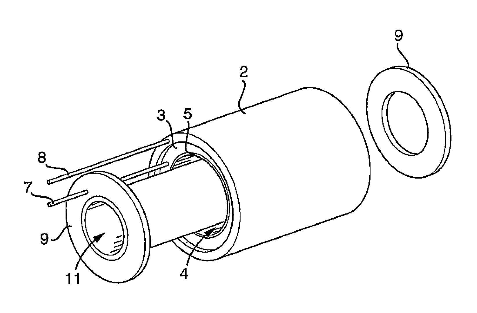
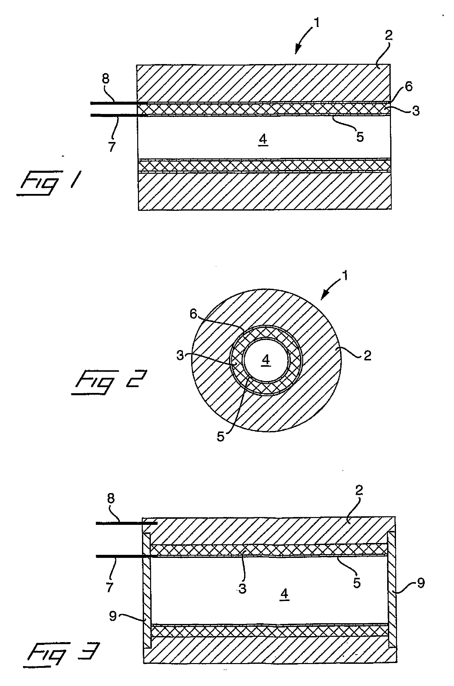
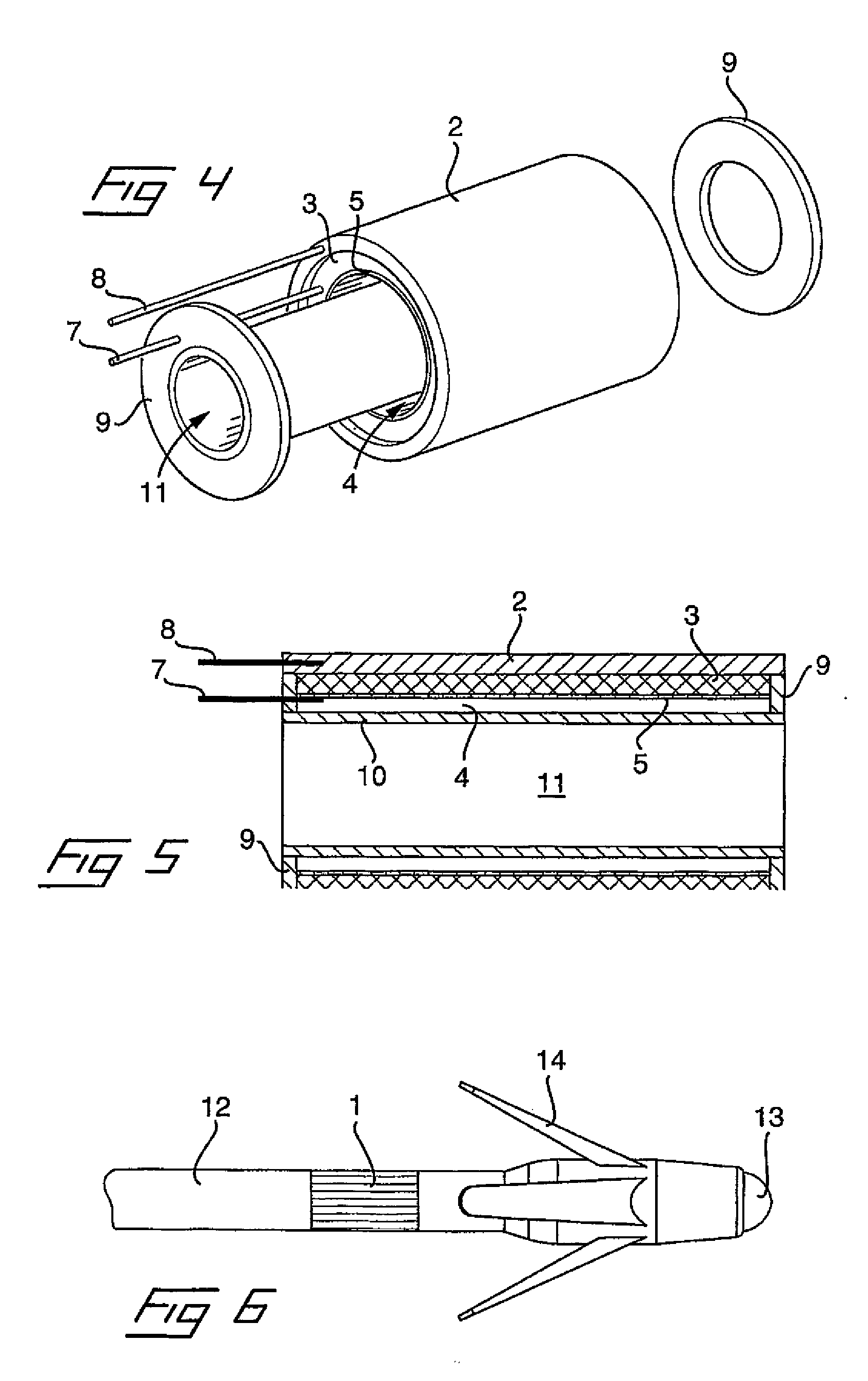
[0025]With reference to FIGS. 1 and 2, a first embodiment of a piezoelectric sensor 1 is illustrated in a longitudinal section and in an end view, respectively. The sensor comprises a supporting substrate 2, which is tubular having a circular cross section. On the inner circumference, the supporting substrate 2 is covered with a piezoelectric layer 3 of a piezoelectric material. Accordingly, the piezoelectric sensor is formed as a tube having a cavity 4 in form of a through bore. To allow the piezoelectric material to serve as a sensor for purpose of measurement, the piezoelectric material is composed of aligned, polarized dipoles in a conventional fashion, well known in the art. In the illustrated embodiment, the supporting substrate is electrically insulating, being formed of for example ceramics or plastics. To detect the electrical signals generated in the piezoelectric layer when exposed to pressure, the piezoelectric layer is provided with an electrode layer 5, 6 on each side....


PUM

PropertyMeasurementUnit
circumferenceaaaaaaaaaa
piezoelectricaaaaaaaaaa
electrically conductingaaaaaaaaaa

Abstract

In a piezoelectric sensor, a method for the manufacture thereof, and an implantable lead embodying such a piezoelectric sensor, a layer of piezoelectric material, having aligned, polarized dipoles, is applied to a tubular supporting substrate, the layer of piezoelectric material having at least one electrode at an outer surface thereof and at least one electrode at an inner surface thereof. The piezoelectric material is applied on the inner circumference of the tubular supporting substrate.

Description

BACKGROUND OF THE INVENTION[0001]1. Field of the Invention[0002]The invention relates to a piezoelectric sensor having a layer of a piezoelectric material being applied to a supporting substrate.[0003]The invention also relates to a method for manufacturing of such a piezoelectric sensor.[0004]The invention also relates to a medical implantable lead comprising such a piezoelectric sensor.[0005]2. Description of the Prior Art[0006]Piezoelectric sensors of the above type are commonly used to detect and measure physical characteristics, such as fluid pressure, stress in mechanical structures and the like. Briefly, piezoelectric sensors transform deformations into electrical signals or pulses. Accordingly, they have a wide applicability and are frequently used in industrial and electronic applications.[0007]A piezoelectric sensor of the above kind, may also be used in many different applications for monitoring various functions and organs inside a human or animal body. As such it may be...

Claims


Application Information

Patent Timeline
Patent Type & Authority Applications(United States)
IPC IPC(8): A61N1/05H01L41/22G01L9/08
CPCG01L9/0026A61N1/36564A61N1/36542A61B5/0215H01L41/1132A61N1/0565Y10T29/42A61N1/056G01L9/08H01L41/087H10N30/60H10N30/302
Inventor ERIKSSON, TOMNILSSON, KENTHHEDBERG, SVEN-ERIK
Owner ST JUDE MEDICAL
Why Eureka
Try Eureka