Forward-section resonator for high frequency dynamic damping

a dynamic damping and forward-section technology, applied in the direction of machines/engines, mechanical equipment, light and heating equipment, etc., can solve the problems of sympathetic vibration, near-by structure to vibrate and ultimately break, and end-of-life failure of such components

Active Publication Date: 2010-01-21
SIEMENS ENERGY INC
View PDF6 Cites 34 Cited by
  • Summary
  • Abstract
  • Description
  • Claims
  • Application Information

AI Technical Summary

Problems solved by technology

If these pressure oscillations, which are sometimes referred to as combustion dynamics, or as high frequency dynamics (“HFD”), reach a certain amplitude they may cause nearby structures to vibrate and ultimately break.
A particularly undesired situation i

Method used


Image

  • Forward-section resonator for high frequency dynamic damping
  • Forward-section resonator for high frequency dynamic damping
  • Forward-section resonator for high frequency dynamic damping

Examples


Embodiment Construction

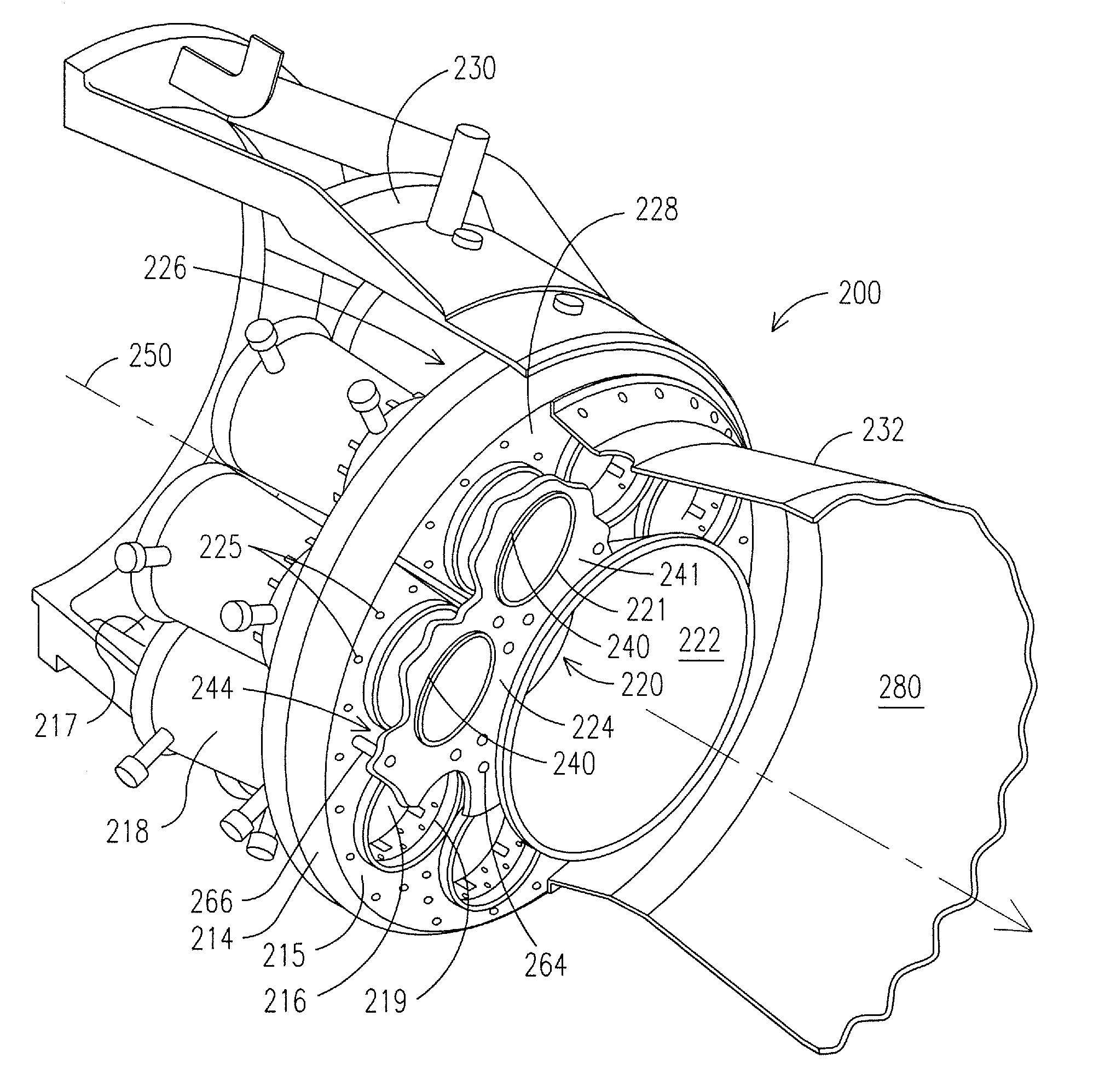
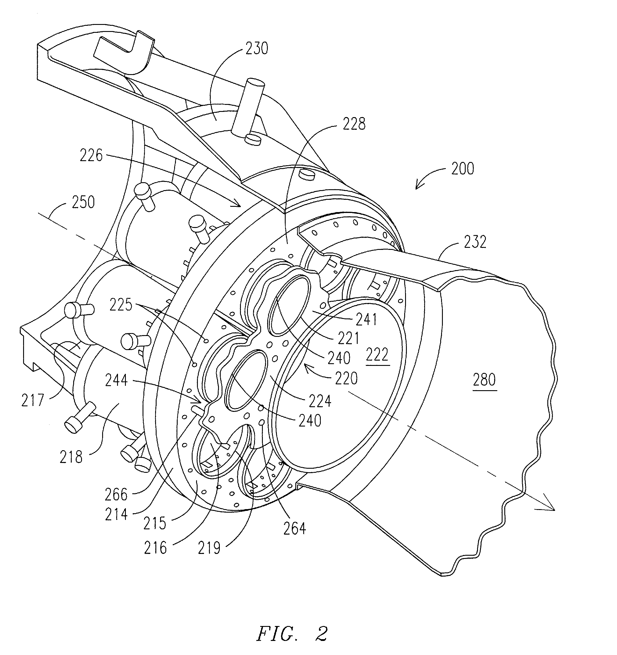
[0018]It is generally appreciated that damping resonators, such as Helmholtz resonators, that are disposed relatively downstream of a primary region of combustion have a disadvantage: the compressed air passing through such resonators, into the hot gas path, represents an inefficient use of such air. This is because such air flowing through the resonator may not be fully used in the combustion process. More upstream resonators, including those described above, often present complex structural additions in a region that already has space demands for a number of components and functions.

[0019]The present inventors have appreciated a solution to providing an effective Helmholtz resonator arrangement by utilizing an annular region in the combustor not previously utilized for such purpose. In various embodiments this also improves performance in ways in addition to vibration damping.

[0020]In many gas turbine combustors there exists an annular region having a primary function of providing...


PUM


Abstract

A gas turbine combustor having a Helmholtz resonator in a post-swirler homogenization zone upstream of the combustor zone. Embodiments of the present invention provide Helmholtz resonators that include cavities that occupy a remainder of a post-swirler homogenization zone, which also includes at least one flow-directing structure that passes a fuel/oxidizer mixture from a main swirler assembly into a combustion zone of a combustor. Thus, an open annular region of the combustor is converted into a multi-purpose zone that includes at least one Helmholtz resonator.

Description

FIELD OF INVENTION[0001]The invention generally relates to a gas turbine engine, and more particularly to a Helmholtz resonator positioned in a particular upstream zone of a combustor of a gas turbine engine.BACKGROUND OF THE INVENTION[0002]Combustion engines such as gas turbine engines are machines that convert chemical energy stored in fuel into mechanical energy useful for generating electricity, producing thrust, or otherwise doing work. These engines typically include several cooperative sections that contribute in some way to this energy conversion process. In gas turbine engines, air discharged from a compressor section and fuel introduced from a fuel supply are mixed together and burned in a combustion section. The products of combustion are harnessed and directed through a turbine section, where they expand and turn a central rotor.[0003]A variety of combustor designs exist, with different designs being selected for suitability with a given engine and to achieve desired per...

Claims


Application Information

Patent Timeline
IPC IPC(8): F02C7/24
CPCF23M20/005F23R2900/00014F23M99/005
Inventor GAMBACORTA, DOMENICOJOHNSON, CLIFFORD E.
Owner SIEMENS ENERGY INC
Why Eureka
Try Eureka