Eureka AIR delivers breakthrough ideas for toughest innovation challenges, trusted by R&D personnel around the world.

Torque power tool

Active Publication Date: 2010-01-21
HYTORC DIV UNEX CORP
View PDF7 Cites 15 Cited by
  • Summary
  • Abstract
  • Description
  • Claims
  • Application Information

AI Technical Summary

Benefits of technology

[0009]Accordingly, it is an object of the present invention to provide a torque power tool which avoids the disadvantages of the prior art.

Problems solved by technology

However, this can not be accomplished with slugging wrenches or impact wrenches.
In known torque power tools with a reaction arm there is a significant risk that during intended use, operator's fingers or hand might be caught between the reaction arm and the abutment area when not paying attention.
This is one of the greatest dangers in bolting with torque power tools, and it happens frequently, since the reaction force applied by the tool is in most cases much larger than the LBS / FT torque as the portion of the reaction arm that abuts is often less than one-quarter of a foot away from the turning axis of the tool.
Injury to the free hand and its fingers known to be severe.
Such accidents occur frequently, and require attention.
So not only has the operator been injured and hurt, but the cost to the job or work task and loss in productivity is enormous.
For that matter, such workforce accidents are normally subject to OSHA reporting requirements.

Method used


Image

  • Torque power tool
  • Torque power tool
  • Torque power tool

Examples


Embodiment Construction

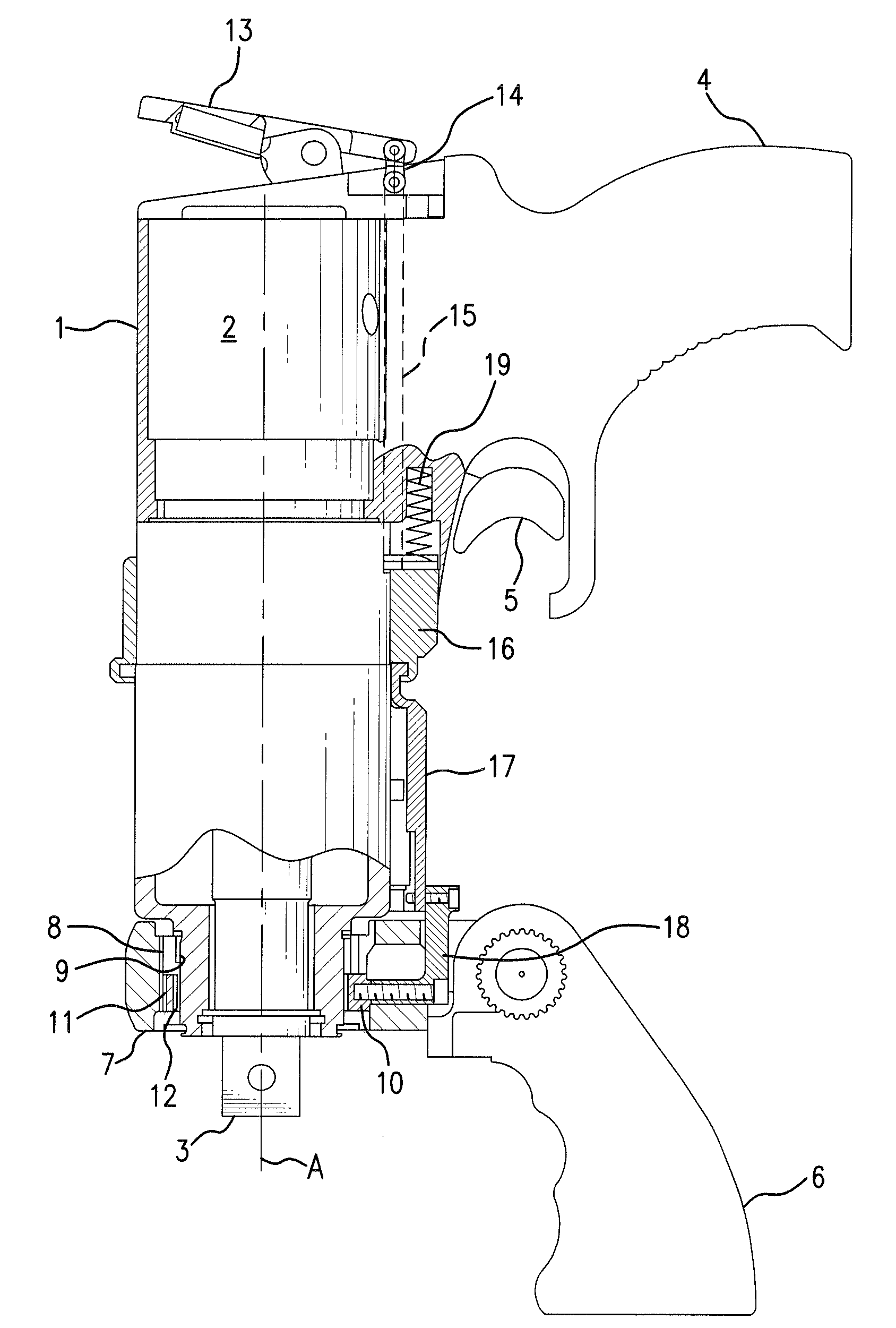
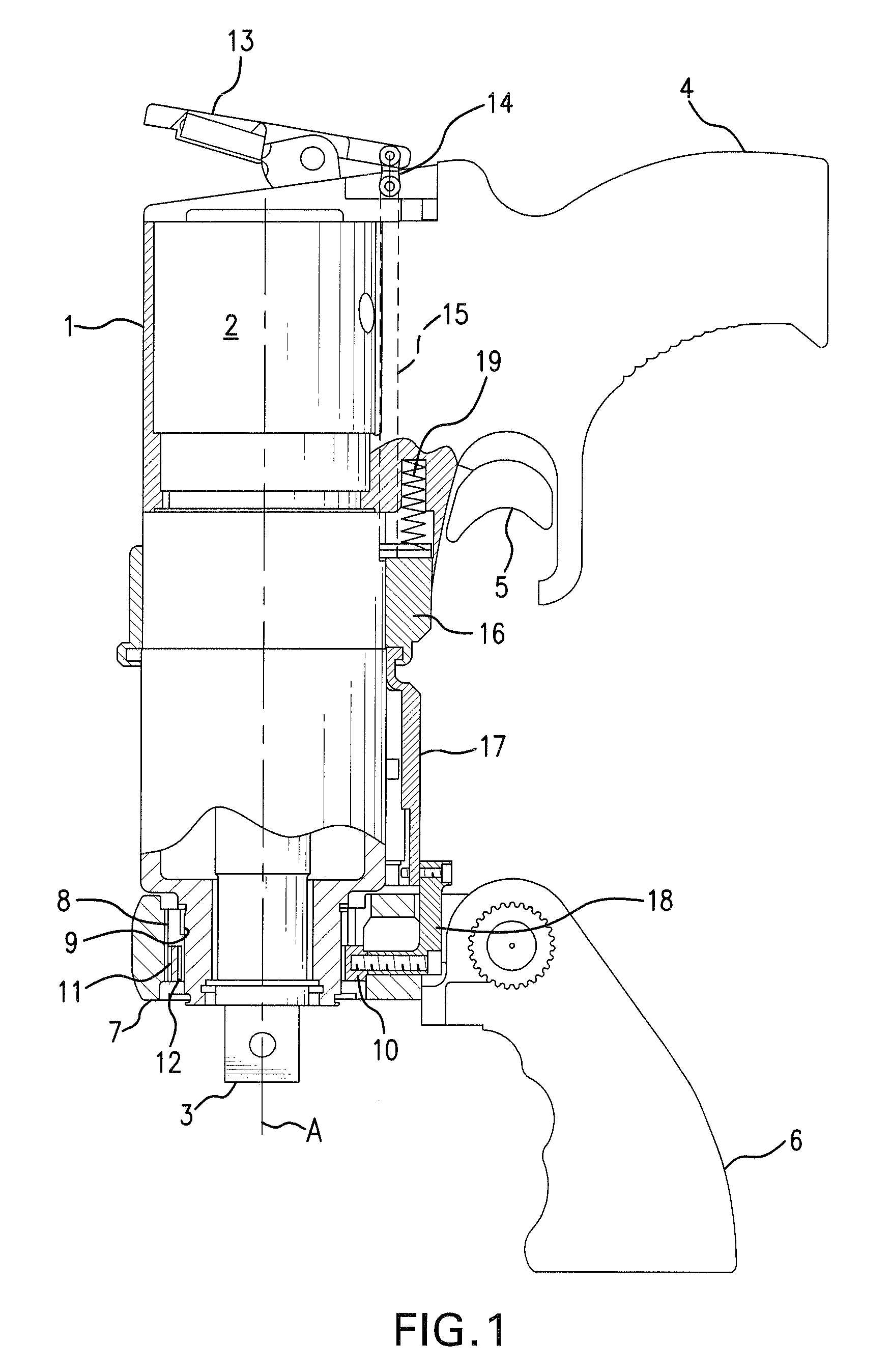
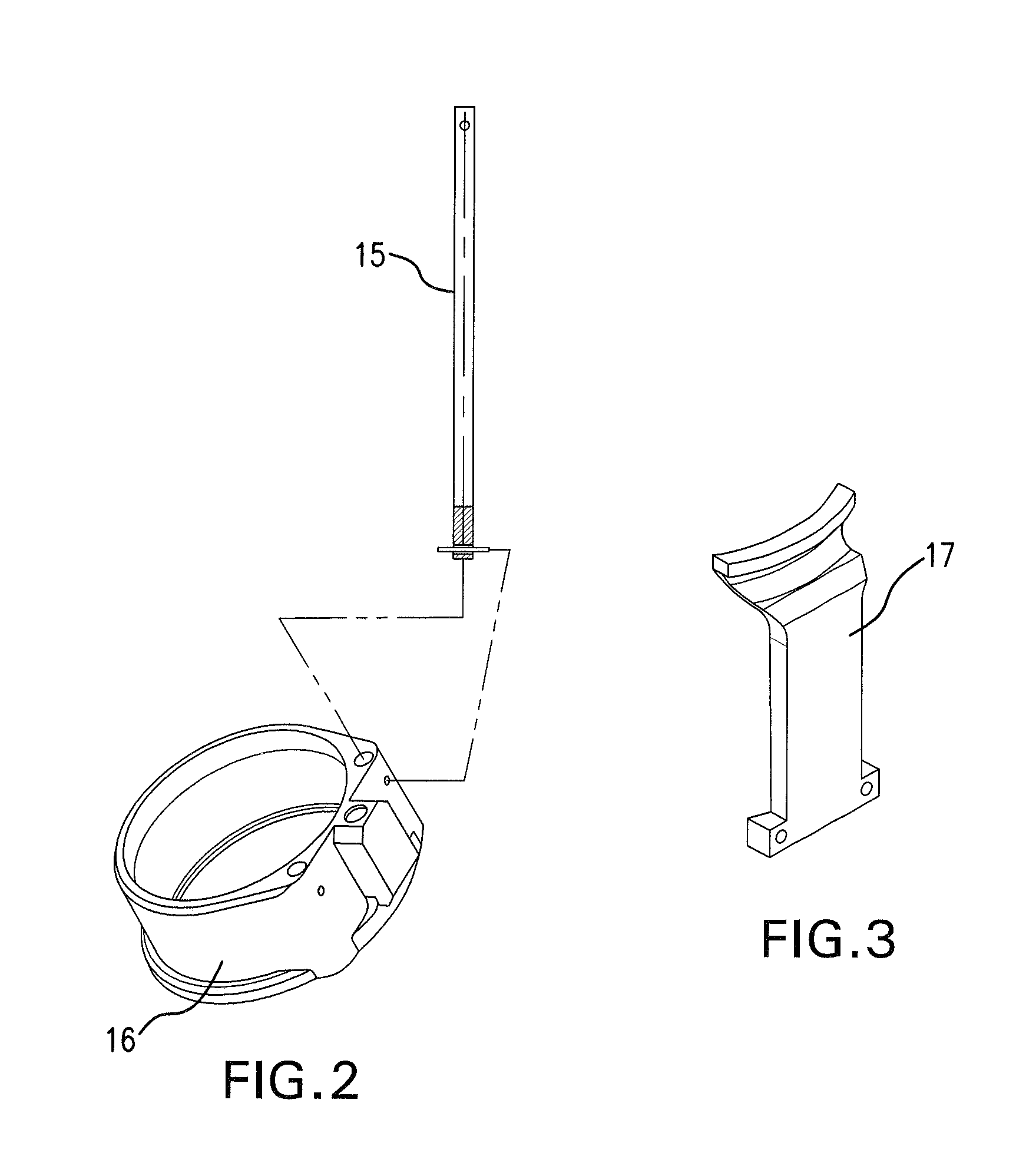
[0023]A hand-held torque power wrench in accordance with the present invention has a housing which is identified with reference numeral 1 and accommodates a motor 2, that can be formed as a hydraulic, pneumatic, electric, etc. motor. A drive element 3 is driven in rotation by the motor 2 and engages a fastener to be tightened or loosened, so that when the motor 2 is actuated, the driving element 3 rotates and provides rotation of a corresponding fastener. The torque power wrench can be provided with torque intensifying means for increasing a torque output from the drive motor 2 to the driving element 3. The torque intensifying means can be formed as planetary gears which are located in the housing 1 and not shown in the drawings.

[0024]The torque power wrench further has a handle 4 for holding the torque power wrench in a position with one hand of an operator, with a trigger 5 for activating the torque power tool with the operator's one hand. The handle 4 is for example immovably con...


PUM


Abstract

A hand-held torque power wrench for tightening and loosening fasteners, the torque power tool has a motor, a housing, at least one handle configured to hold the torque power wrench in a position and to pull a trigger with one hand of an operator, and a safety device operatable by the other hand of the operator, so that when it is operated by the other hand of the operator the torque power wrench is functioning to tighten or loosen the fastener, but when the only one hand of the operator is used for holding the torque power wrench in position and pulling the trigger, the torque power wrench is not functioning to tighten or loosen the fastener.

Description

CROSS REFERENCE[0001]This application claims the benefit of priority of U.S. Provisional Patent Application Ser. No. 61 / 081,765 filed Jul. 18, 2008 under 35 USC 119(e). The subject matter of the aforesaid U.S. Provisional Patent Application is further explicitly incorporated herein by reference thereto.BACKGROUND OF THE INVENTION[0002]The present invention relates to torque power tools.[0003]Power tools are known in the art. One of such known tools is a pneumatic torque power tool. Other torque power tools are known to be driven electrically, hydraulically, manually or otherwise powered. Every torque power tool has an action force and an equal and opposite reaction force. In any of torque tools such as a pneumatic torque tool, a torque multiplier, an electric or hydraulic torque tool, the action force equals a reaction force in opposite direction. As tightening of fasteners is becoming a more precise art, accurate or at least even bolt loads is a requirement. However, this can not b...

Claims


Application Information

Patent Timeline
IPC IPC(8): B25B21/00
CPCB25B23/0078B25B21/00
Inventor JUNKERS, JOHN K.
Owner HYTORC DIV UNEX CORP
Why Eureka
Eureka Blog
Learn More