
Load monitoring and control system with selective boom-up lockout

a monitoring and control system technology, applied in the direction of load-engaging elements, safety gear, cranes, etc., can solve the problems of varying the limit of the permissible range of movement of the crane and its load, the load may be too heavy, and many cranes are not equipped with lmi systems, so as to achieve the effect of reducing the condition

Active Publication Date: 2010-01-21
MANITOWOC CRANE CO LLC
View PDF7 Cites 17 Cited by
  • Summary
  • Abstract
  • Description
  • Claims
  • Application Information

AI Technical Summary

Benefits of technology

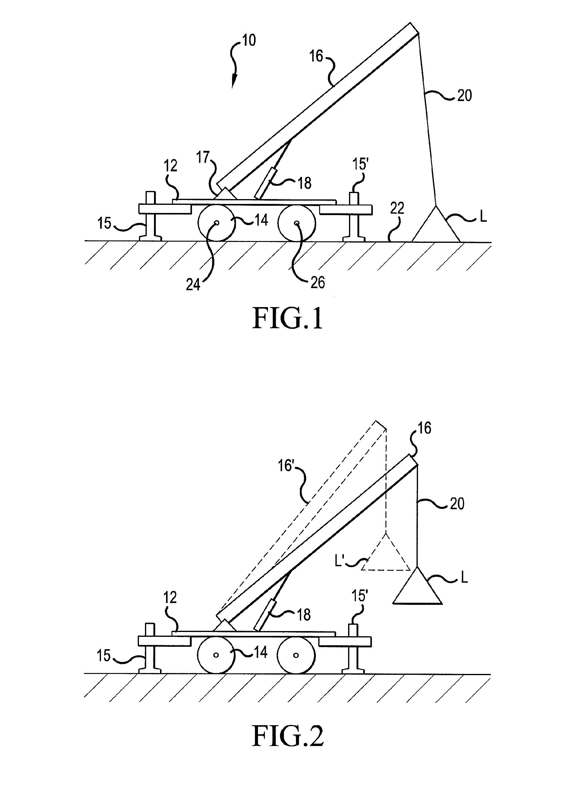
[0003]A typical undesirable crane operation is when an operator attempts to raise a grounded load (a load resting on the ground or some other support) that is too heavy. The load may be “too heavy” because the mass of the load is too great in view of, for example, the length and position of the boom, the distance at which the load is positioned from the base of the crane, and the configuration and dimensions of the supporting base for the crane. In such a situation, an operator might consider attempting to remedy the situation by raising the boom of the crane (an operation often identified as “boom up” or “derrick in”) to thereby move the load closer to the supporting base of the crane, thus reducing the forces that might tend to destabilize the crane.

Problems solved by technology

For each configuration of the crane there will be appropriate capacity limitations including some maximum permissible load which can be lifted or supported by the crane, and a varying limit on the permissible range of movement of the crane and its load for loads of varying magnitudes.
A typical undesirable crane operation is when an operator attempts to raise a grounded load (a load resting on the ground or some other support) that is too heavy.
The load may be “too heavy” because the mass of the load is too great in view of, for example, the length and position of the boom, the distance at which the load is positioned from the base of the crane, and the configuration and dimensions of the supporting base for the crane.
Many cranes are not equipped with an LMI system which would prevent a boom up operation.
However, it can have the drawback of conditioning operators to routinely and too often override lock out functions, thus developing what might be characterized as an override habit.
That circumstance creates a danger that an operator will, too readily and / or too frequently override a function lock out without sufficient consideration when it may be undesirable to do so.
Accordingly, it is not desirable to encourage or require a boom operator to override a function lock out too often or unnecessarily.
An override by the operator would be required in every instance in which such operation was sensed, which may lead to an undesirable override habit as discussed above.

Method used


Image

  • Load monitoring and control system with selective boom-up lockout
  • Load monitoring and control system with selective boom-up lockout
  • Load monitoring and control system with selective boom-up lockout

Examples


Embodiment Construction

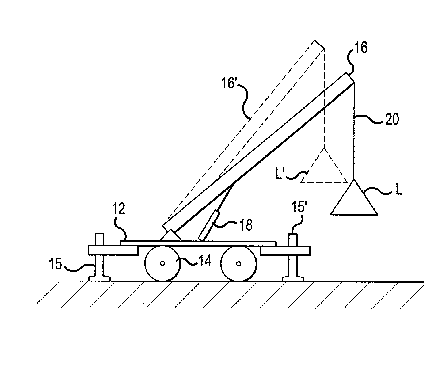
[0016]FIG. 1 schematically illustrates a crane 10. The crane comprises a base 12 typically supported on, for example, a pair of wheels 14. Various cranes may be supported upon tracked transport means. During lifting operations, many cranes employ, for example, outriggers 15, 15′ for providing a wider and more stable support base for the crane, counterweights (not shown), etc. Other configurations of cranes are known, and the invention is not limited to the example schematically illustrated.

[0017]A crane typically includes a boom 16 which is pivotally connected to the base of the crane in the vicinity of point 17, and which may be raised and lowered by a lift cylinder 18. The cylinder 18 is operated by hydraulic means, as is well known. A cable 20 is provided for lifting loads, represented in FIG. 1 as L. A hook (not shown) is typically provided for engaging the load, which is raised and lowered by taking in and paying out cable 20 via a powered winch (not shown) in a well known mann...


PUM


Abstract

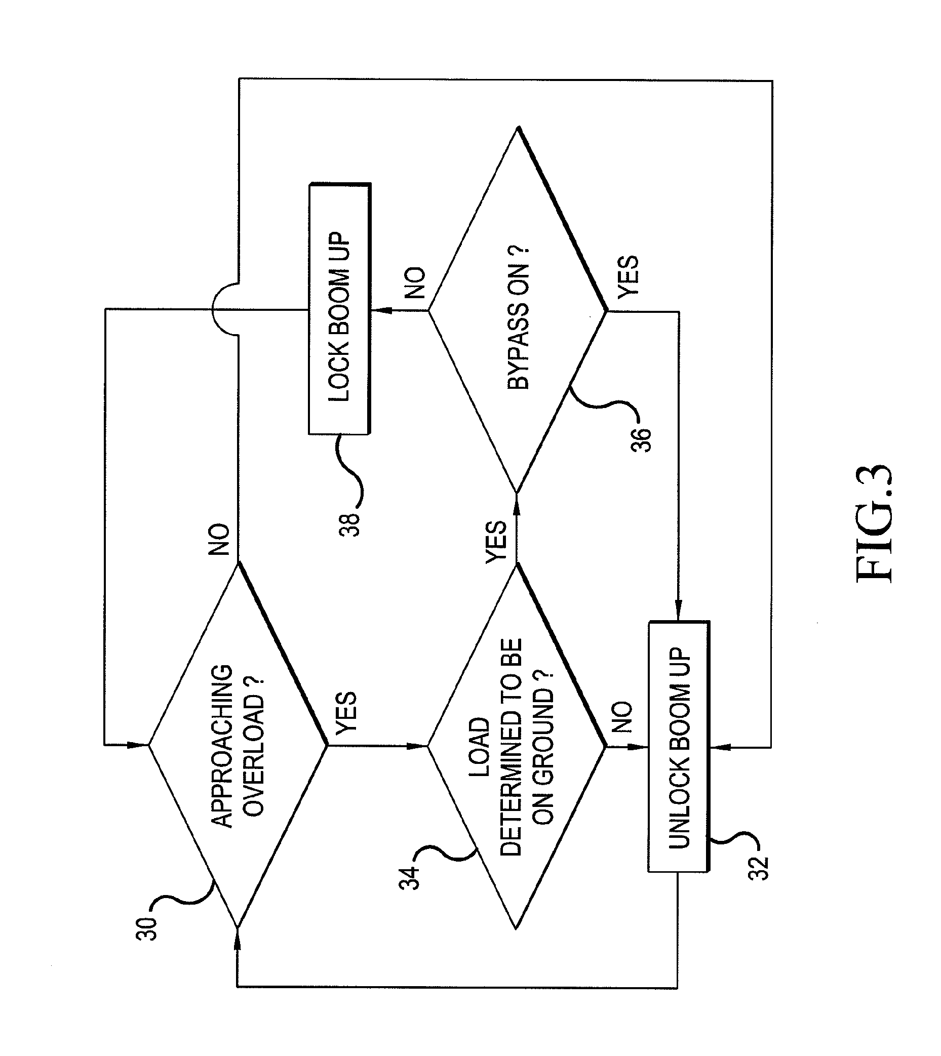
A method is disclosed for controlling a crane which comprises a boom that may be raised or lowered by angular adjustment of the boom about a base portion of the crane. The method prevents operation of the crane in an undesired condition by continuously monitoring operation of the crane, including monitoring at least the position of the boom with respect to the base of the crane. If the crane approaches a limit of its operating range or any operational parameter, its operation will be controlled so as to selectively prohibit or permit a boom raising operation of the crane, depending on the cause of the condition, rather than uniformly prohibit such an operation.

Description

[0001]Systems that monitor loads on a crane and control the crane in accordance with sensed conditions, and components of such systems, are referred to by various terms. These include Load Moment Limiters, Rated Capacity Indicators, Rated Capacity Limiters, Load Indicators, Safe Load Indicators, Load Moment Indicators, etc. Each of these may be a system, or part of a system that monitors loads on a crane in order to assist an operator to operate the crane only within recommended or desired parameters. For the sake of brevity, all such systems will be referred to hereinafter as Load Moment Indicator (LMI) systems.[0002]Typically, an LMI system receives data indicating the configuration of the crane, including such factors as boom length, boom angle, configuration and dimensions of the outriggers or other supporting base for the crane, mass and position of counterweights, etc. The LMI further monitors the load on a crane at each instant of time. For each configuration of the crane the...

Claims


Application Information

Patent Timeline
Patent Type & Authority Applications(United States)
IPC IPC(8): B66C13/04
CPCB66C23/905B66C13/46B66C15/00B66C13/18
Inventor RUDY, JOHN R.
Owner MANITOWOC CRANE CO LLC
Learn More