High speed clock and data recovery system

a high-speed clock and data recovery technology, applied in the field of communication devices, can solve the problems of circuits that may falsely lock to spurious tones and harmonics of data signals, analog pll circuits are susceptible to instability, and can not meet the requirements of high-speed communications, so as to quickly mitigate the condition and mitigate the meta-stability condition

Inactive Publication Date: 2006-11-14
AVAGO TECH INT SALES PTE LTD
View PDF7 Cites 51 Cited by
  • Summary
  • Abstract
  • Description
  • Claims
  • Application Information

AI Technical Summary

Benefits of technology

[0013]In accordance with aspects of the invention, a clock and data recovery system is provided that can detect and rapidly mitigate meta-stability conditions. The clock and data recovery system includes a sampling module, a phase detector, a gain adjust module, a phase accumulator, and a phase interpolator coupled in series. The output of the phase interpolator is feedback as input to the sampling module. The phase detector includes meta-stability resolution logic that is configured to determine when a meta-stability condition is occurring and to generate an output signal to rapidly mitigate the condition.
[0015]In accordance with further aspects of the invention, a phase interpolator having improved linearity is provided. The phase interpolator includes a plurality of first branches, each having a differential transistor pair, a switch, and a current source, coupled between a first output and a first supply voltage and a plurality of second branches, each having a differential transistor pair, a switch, and a current source, coupled between a second output and the first supply voltage. The phase interpolator also includes a first resistance coupled between the second supply voltage and the first output and a second resistance coupled between the second supply voltage and the second output. In a further aspect, the phase interpolator includes a integrator portion coupled to the plurality of first branches and the plurality of second branches.

Problems solved by technology

These analog PLL circuits have several limitations.
Because the circuits typically are implemented using a high order loop and have a loop gain that depends upon the signal transition density, analog PLL circuits are susceptible to instability.
Also, because these circuits have unrestrained frequency acquisition characteristics, the circuit may falsely lock to spurious tones and harmonics of the data signal.
Because the characteristics of the delay module vary with process, temperature, and supply voltage variations, this type of DLL is difficult to design for mass production and thus, has a limited range of applications.
In addition, analog implementations that allow different loop bandwidths in the acquisition and tracking phase require more complexity than the conventional analog CDRs described above and are still susceptible to degradations caused by process, temperature and voltage variation.
However, a small loop bandwidth also means a slow response time during the acquisition phase.
A slow response time during acquisition limits the use of these DLL circuits in applications where the synchronization sequence preceding the data is restrictively short.
In these implementations, because the phase of the delayed signal cannot be fed back, this type of DLL is restricted to a limited frequency and phase capture range of operation.
This limitation is further exacerbated by the fact that the delay in each element varies with temperature, process variation, and power supply voltage.
Thus, the ability to obtain adequate phase and frequency capture is made increasingly difficult.
Also, for a long tapped delay line, jitter is accumulated as the signal is passed through the numerous delay elements.
Thus, if the last few tapped delay lines are used, high self-induced jitter results.
Another potential limitation of using conventional digital or analog CDR circuits, such as those described above, is the possibility that a state could occur such that the phase of the recovered clock is not moved in any direction (referred to as a “dead state” or “meta-stability condition”).
A dead state could occur when the synchronization sequence has jitter and duty clock distortion and the clock is not aligned correctly.
This effect is undesirable in systems where the number of synchronizations cycles is small and fast acquisition or locking response is required.

Method used


Image

  • High speed clock and data recovery system
  • High speed clock and data recovery system
  • High speed clock and data recovery system

Examples


Embodiment Construction

I. High Speed, Fast Acquisition and Low Jitter Tracking CDR System

A. System Architecture

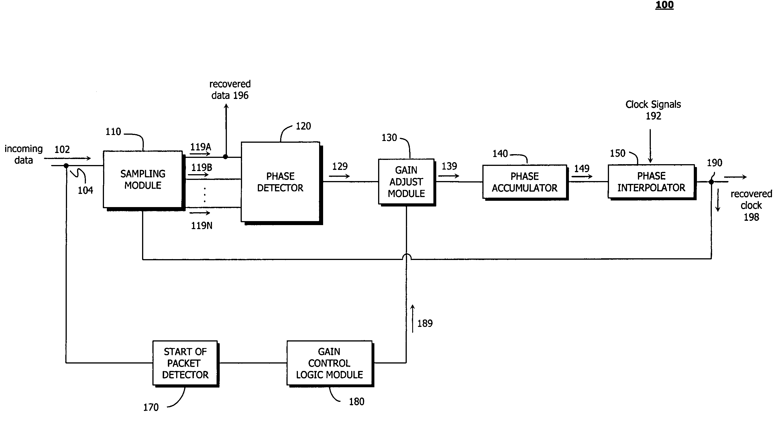
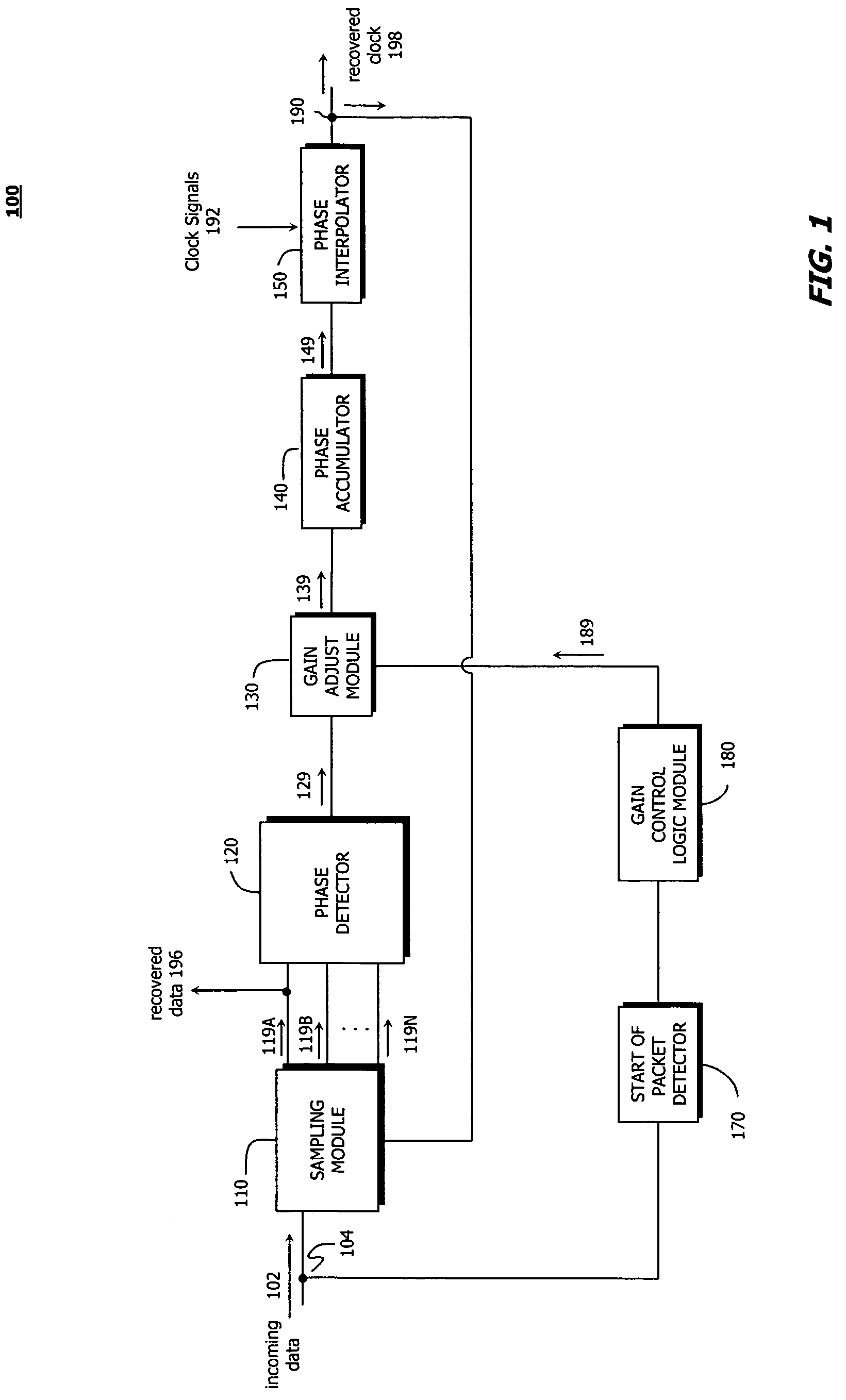
[0040]FIG. 1 is a block diagram of a high speed clock and data recovery (CDR) system 100 using a first-order digital delay-locked loop (DLL), according to embodiments of the present invention. CDR system 100 provides time varying gain adjustment, allowing high loop gain in the acquisition stage for fast phase locking and small loop gain in the tracking mode for good jitter rejection. CDR system 100 includes a sampling module 110, a phase detector 120, a gain adjust module 130, a phase accumulator 140, and a phase interpolator 150 coupled in series between CDR system input 104 and output 190. CDR system 100 also includes an optional start of packet detector 170 and an optional gain control logic module 180 coupled between CDR system input 104 and gain adjust module 130.

[0041]In system 100, sampling module 110 receives the incoming data signal 102 and the recovered clock signal 198 generated by pha...


PUM


Abstract

A clock and data recovery system for detecting and resolving meta-stability conditions is provided. The clock and data recovery system includes a phase detector having logic configured to detect a meta-stability condition and to generate an output signal to mitigate the condition. The system can also include a time varying gain adjustment portion. This portion includes a gain control logic configured to determine and adjust system gain during reception of an incoming data stream. The system further includes a phase interpolator having increased linearity. The phase interpolator has a plurality of first branches having a differential transistor pair, a switch, and a current source, coupled between a first output and a first supply voltage and a plurality of second branches having a differential transistor pair, a switch, and a current source, coupled between a second output and the first supply voltage. The phase interpolator can also include an integrator portion.

Description

FIELD OF THE INVENTION[0001]The present invention is generally related to communication devices and in particular to a system and method for recovery of timing information and data for high speed communications links.BACKGROUND OF THE INVENTION[0002]In the past decade, there has been a dramatic increase both in processor speeds and in memory capacity. As a result, the need for networks to handle high-speed transfer of large quantities of data among devices has also increased. Transceivers capable of efficiently receiving and transmitting high-speed data are critical components of these high-speed networks.[0003]To reliably process a received data signal, a receiver must match its operating characteristics to the characteristics of the received data signal. For example, to minimize data recovery errors, a receiver generates a clock signal to sample the received data signal at times that produce optimal data recovery. To achieve this optimal data recovery, the receiver must lock the s...

Claims


Application Information

Patent Timeline
Patent Type & Authority Patents(United States)
IPC IPC(8): H03H11/16
CPCH03K5/13H03L7/0814H03L7/091H03L7/107H04L7/0337H03K2005/00052H04L7/0025
Inventor TEO, TIAN HWEEHO, DAVID SENG POH
Owner AVAGO TECH INT SALES PTE LTD
Why Eureka
Try Eureka