Positioning system, device, and method for in-flight refueling

Active Publication Date: 2006-01-05
THE BOEING CO
View PDF4 Cites 47 Cited by
  • Summary
  • Abstract
  • Description
  • Claims
  • Application Information

AI Technical Summary

Benefits of technology

[0010] The embodiments of the present invention also provide a method for facilitating the in-flight spatial positioning of a first aircraft with respect to a second aircraft. According to some advantageous embodiments the method comprises the steps of: sending a signal from a positioning device carried by the first aircraft, the positioning device being configured such that the signal it sends is receivable by the second aircraft, and guiding the second aircraft, in response to the signal, to an in-flight refueling position relative to the first aircraft.
[0011] Advantages provided by embodiments of the present invention may include, but are not limited to, the ability to accurately guide the second aircraft into the in-flight refueling p

Problems solved by technology

The requirement of precise relative spatial positioning of two rapidly moving aircraft, makes in-flight refueling a challenging operation.
As refueling drogues, however, have proven relatively unmaneuverable, these systems have not been operationally viable.
Other optical systems for positioning objects with respect to reflectors and retro-reflectors have not been easily adapted for use in all types of in-flight refueling systems.
In addition, optical landing aids, such as visual approach slope indicator (VAST) systems, are useful for providing optical glide slope information for aircraft approaching a fi

Method used


Image

  • Positioning system, device, and method for in-flight refueling
  • Positioning system, device, and method for in-flight refueling
  • Positioning system, device, and method for in-flight refueling

Examples


Example

[0031] The present inventions now will be described more fully hereinafter with reference to the accompanying drawings, in which some, but not all embodiments of the invention are shown. Indeed, these inventions may be embodied in many different forms and should not be construed as limited to the embodiments set forth herein; rather, these embodiments are provided so that this disclosure will satisfy applicable legal requirements. Like numbers refer to like elements throughout.

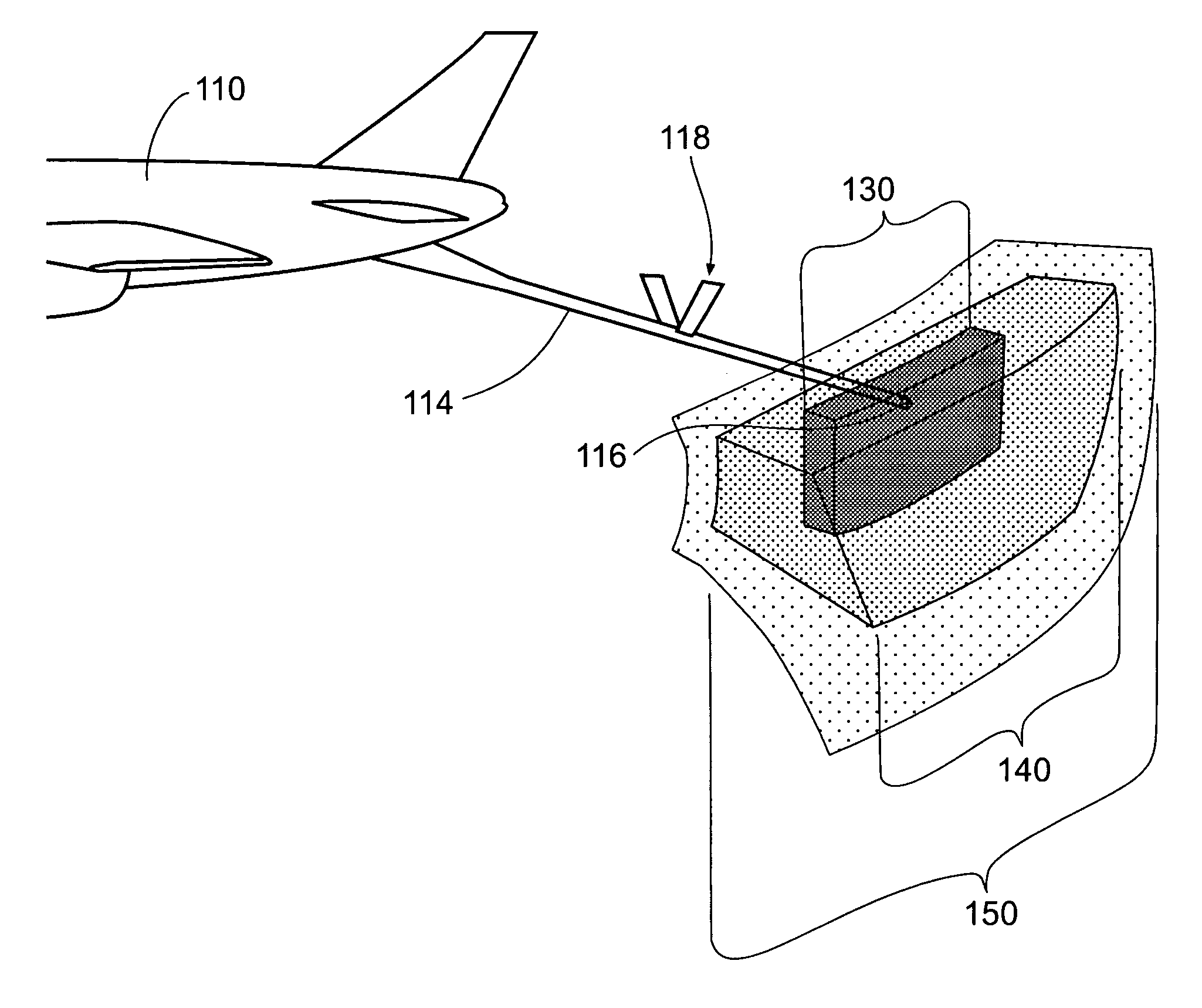
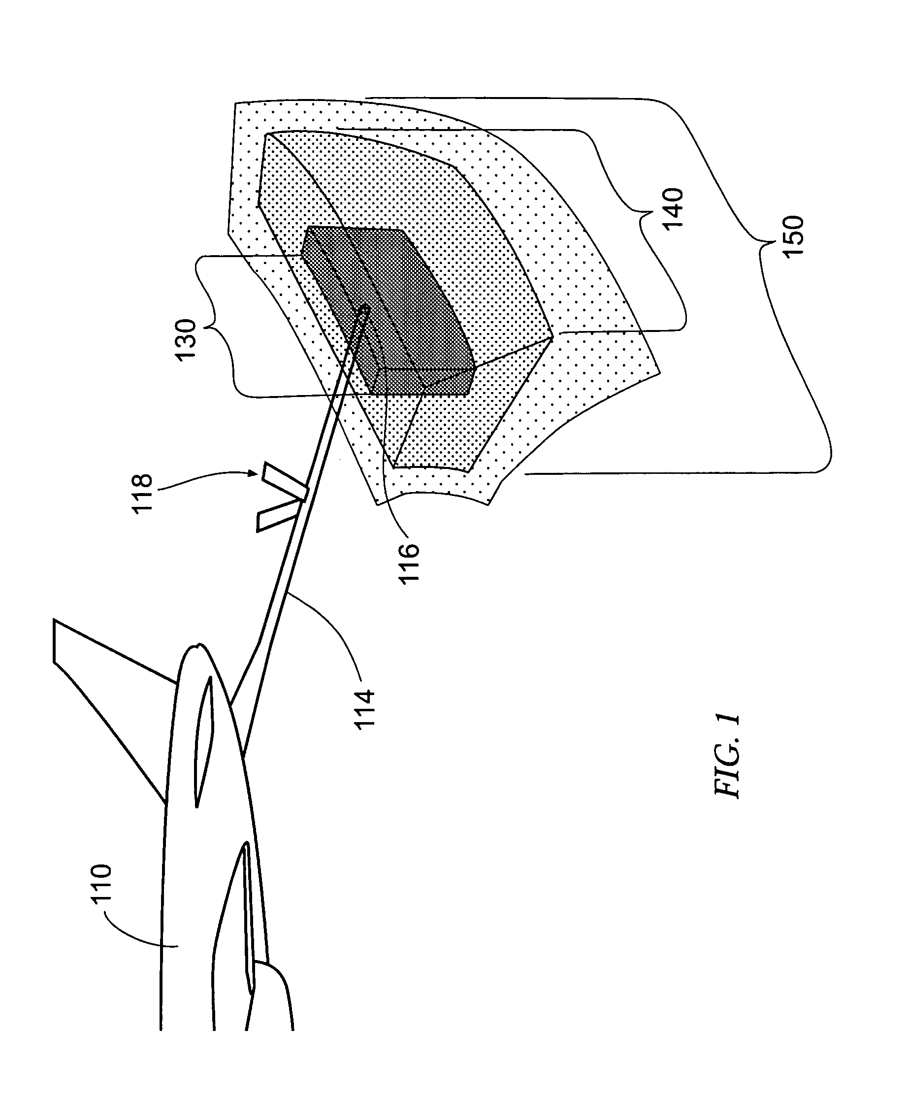
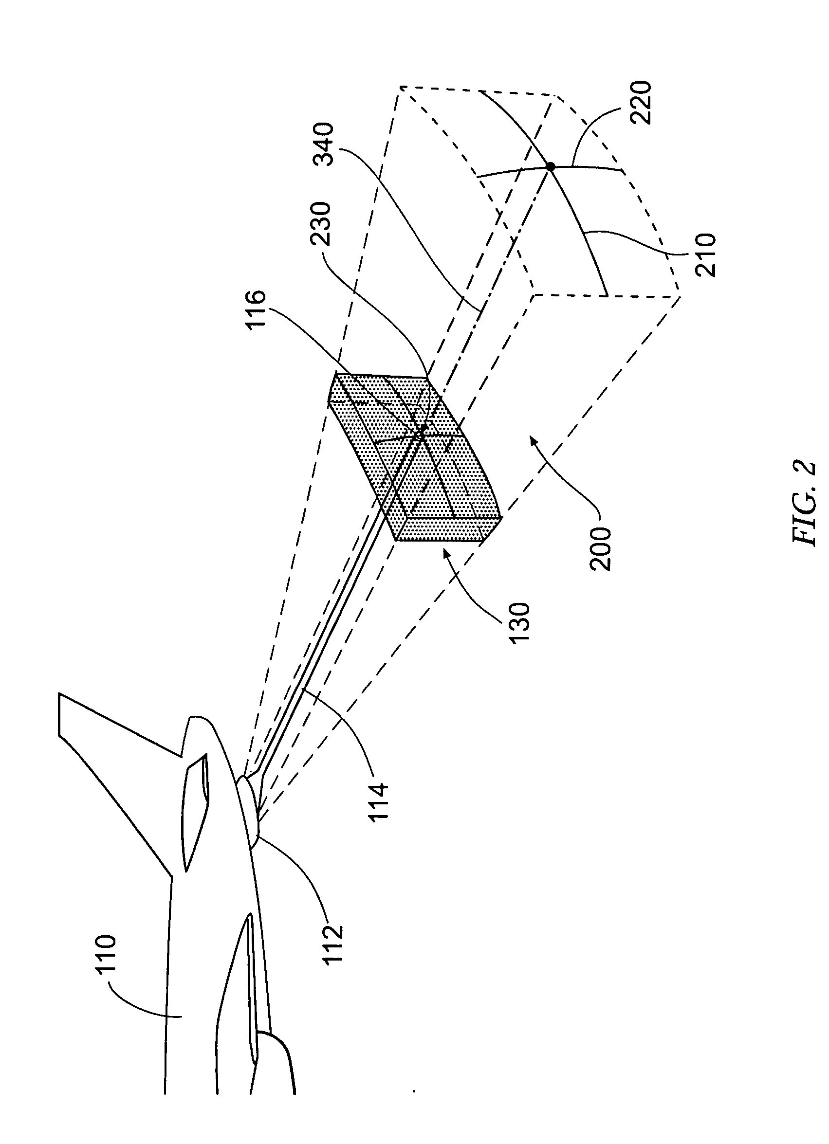
[0032] While the positioning system, device, and method embodiments of the present invention are described below in the context of in-flight refueling operations involving a first aircraft 110 (serving as a tanker aircraft) and a second aircraft 120 (serving as a receiver aircraft), it should be understood that the embodiments of the present invention may also be utilized to achieve the relative in-flight spatial positioning of a first and second aircraft for a variety of in-flight operations, including, but ...


PUM


Abstract

A positioning system, device, and method are provided to facilitate the in-flight positioning of two aircraft relative to one another such that a second aircraft is guided to an in-flight refueling position relative to a first aircraft. The system, device, and method of the present invention provide a signal emitted from a positioning device carried by the first aircraft, wherein the signal defines a signal envelope containing the in-flight refueling position. The signal is adapted to be receivable by the second aircraft such that the signal may guide the second aircraft to the in-flight refueling position relative to the first aircraft.

Description

FIELD OF THE INVENTION [0001] The present invention relates generally to in-flight refueling, and specifically, providing optical and / or electronic positioning devices on a first aircraft so as to provide guidance to a manned or unmanned second aircraft such that the first and second aircraft may be spatially positioned, relative to one another, for in-flight refueling. BACKGROUND OF THE INVENTION [0002] In-flight refueling (or air-to-air refueling) is an important method for extending the range of aircraft traveling long distances over areas having no feasible landing or refueling points. Although in-flight refueling is a relatively common operation, especially for military aircraft, precise positioning of a second aircraft (the receiver aircraft, for example) with respect to a first aircraft (the tanker aircraft, for example) is required in order to provide a safe engagement of the first aircraft with the second aircraft for the dispensing of fuel. The requirement of precise relat...

Claims


Application Information

Patent Timeline
IPC IPC(8): B64D39/00
CPCB64D39/00
Inventor SCHROEDER, STEVEN B.
Owner THE BOEING CO
Why Eureka
Try Eureka