Method for mitigating rod float in rod pumped wells

a technology of pumped wells and rods, applied in the direction of pump parameters, motor parameters, pump control, etc., can solve the problems of less successful arrangement in practice, and achieve the effect of minimizing production and reducing damage to equipmen

Active Publication Date: 2006-03-30
RAVDOS HLDG INC
View PDF3 Cites 53 Cited by
  • Summary
  • Abstract
  • Description
  • Claims
  • Application Information

AI Technical Summary

Benefits of technology

[0006] A primary object of the invention is to provide Rod Float Mitigation (RFM) methods to detect rod float during ro...

Problems solved by technology

A proximity switch to detect separation of the carrier bar from the polished rod clamp may be used although ...

Method used


Image

  • Method for mitigating rod float in rod pumped wells
  • Method for mitigating rod float in rod pumped wells
  • Method for mitigating rod float in rod pumped wells

Examples


first embodiment

Fixed Speed Option

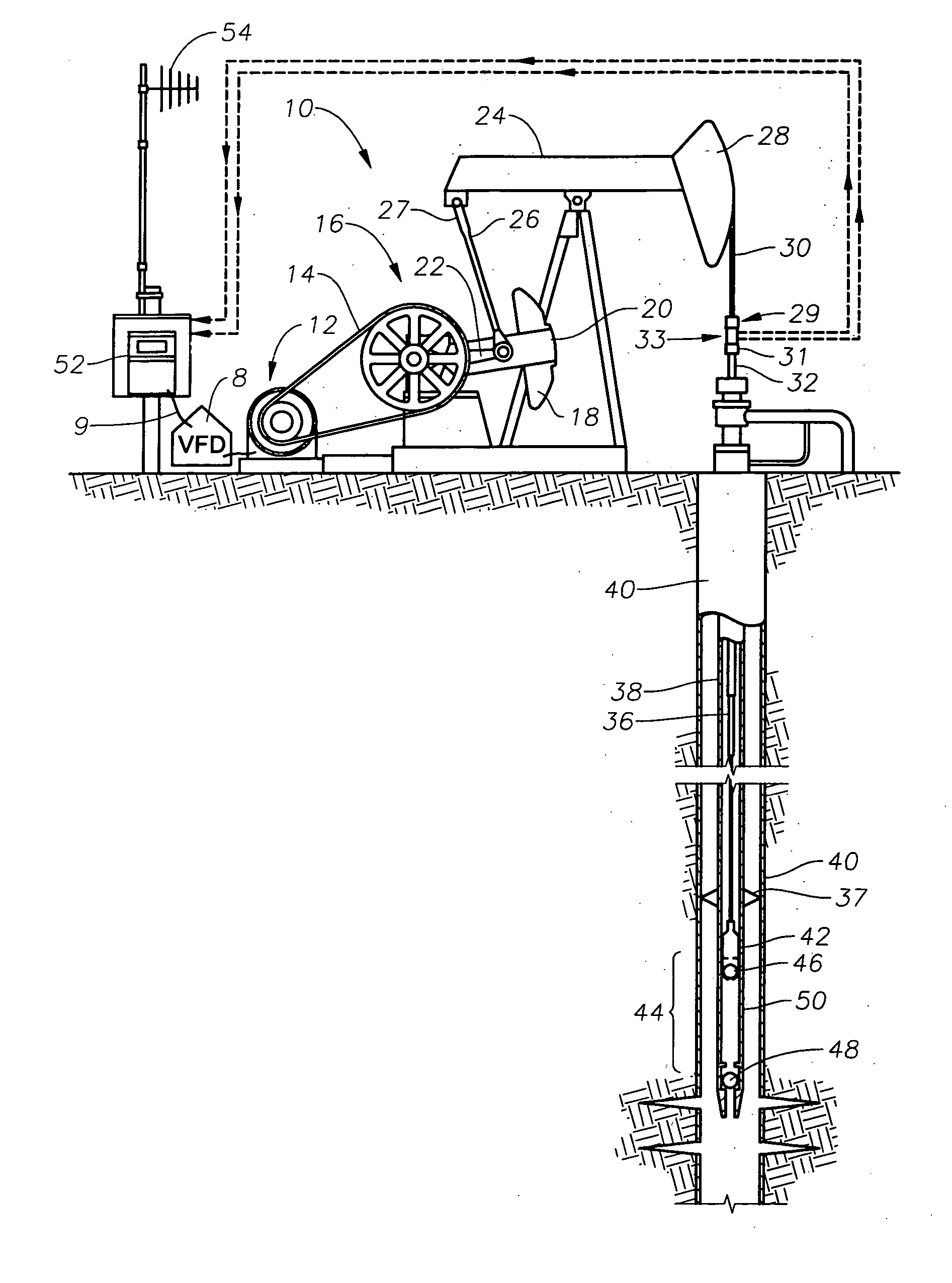
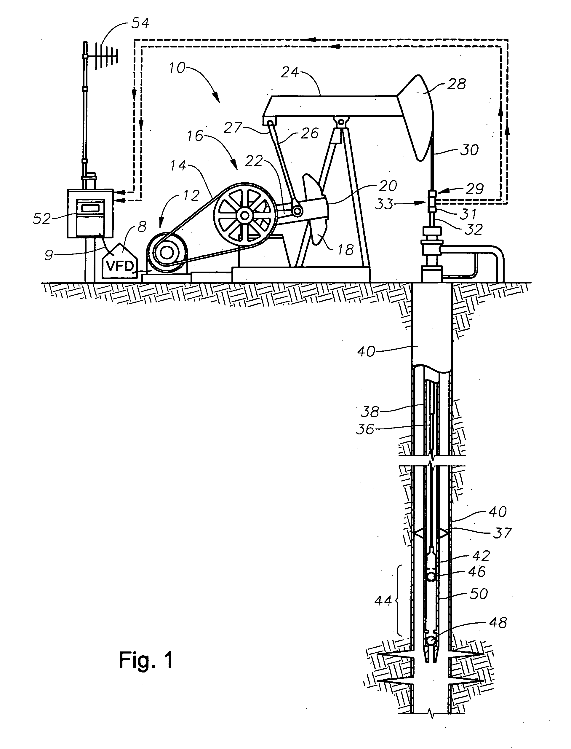
[0031] When software in the controller 52 (see FIG. 1) senses a low load signal from the surface card (e.g., loads below 200 lbs.), a digital output is sent via signal path 9 to the VFD 8, which may activate a rod float mitigation procedure according to a first embodiment. The VFD 8 controls the speed of prime mover 12 to a preset or fixed reduced value so long as the low load signal is present on signal path 9. Alternatively, the controller 52 detects the low load condition and changes the command speed being sent to the VFD 8 via signal path 9.

second embodiment

Fixed Torque Option

[0032] When software in the controller 52 senses a low load signal from the surface card (e.g., loads below 200 lbs.), a digital output is sent via signal path 9 to the VFD 8, which may activate a rod float mitigation procedure in software in the VFD 8 according to a second embodiment. Net gear box torque is a function of the motor speed and geometry of the mechanical linkage between motor 12 and the rod pump assembly, 32, 36, 42. VFD speed control to the motor is adjusted such that the calculated net gear box torque will not exceed a programmed fixed torque limit as is illustrated in FIG. 6b. In other words, the speed is slowed to a level such that the gear box curve 120 does not exceed the level labeled as RFM Fixed Torque Level. This method reduces any time lag between initiation of the low load signal and action on the part of the VFD 8 to match the pumping unit motion with the polished rod 32 fall.

[0033] Alternatively, software in the controller 52 can dete...

third embodiment

Variable Torque Curve Option

[0034] According to a third embodiment of the invention, a method is incorporated in software of the controller of FIG. 1 for controlling the variable frequency drive (VFD) 8 to mitigate rod float of the pumping unit 10. The definitions of parameters and measurements used in the method are as follows:

Tcounterbalance=M* sin(Θbottom of stroke+RK*(Θoffset+τ))

Tnet gb (at slow speed shaft)=Tmotor*NREVref

[0035] Tcounterbalance Torque applied at slow speed crank shaft 22 of gearbox 16 due to counterbalance weight 18 and crank weight 20 (in-lbs)

[0036] Tnet gb (at slow speed shaft) Effective torque applied at slow speed crank shaft 22 due to motor 12 torque transmitted to gearbox 16 through drive train (in-lbs)

[0037] M Maximum counterbalance moment, cranks at 90 degrees (in-lbs); provided by CONTROLLER 52

[0038] RK rotation key ±1 depending on unit rotation (CW, CCW) and unit type; provided by CONTROLLER 52

[0039]Θoffset angle between 6 o'clock position (vertical...


PUM


Abstract

Rod Float Mitigation (RFM) methods for rod-pumped oil wells having a variable frequency drive which controls the speed of the motor for the pump. Each method monitors rod loads or a similar condition and takes action only when rod load drops below a predefined minimum load. A first method reduces the speed of the motor to a preset level. A second method fixes the torque level on the pump downstroke by adjusting motor speed based on a calculated gearbox torque compared to a programmed fixed limit. Another method includes a program in the variable frequency drive which includes a preferred RFM Torque Curve for the pump to follow on its downstroke. When rod float occurs, the program monitors gearbox torque and adjusts the speed to follow the predetermined RFM Torque Curve thereby mitigating rod float with minimum decrease in production.

Description

REFERENCE TO PREVIOUS APPLICATION [0001] This Non-Provisional Application is based on Provisional Application 60 / 611,148 filed on Sep. 9, 2004 and claims the benefit of that filing date.BACKGROUND OF INVENTION [0002] 1. Field of the Invention [0003] This invention relates in general to control of rod pumped wells and in particular to control of rod pumping equipment for conditions where heavy crude oil production creates viscous and rod drag forces that cause the rod string to fall slower than the pumping unit motion on the downstroke. [0004] 2. Description of the Prior Art [0005] When heavy crude oil production creates viscous and rod drag forces that cause the rod string to fall slower than the pumping unit downstroke motion, the pumping unit equipment can be damaged resulting in excessive maintenance costs and reduced production. A prior solution to that problem has been to install a variable frequency drive on the pumping unit and to manually slow the motor speed so that the pum...

Claims


Application Information

Patent Timeline
IPC IPC(8): F04B49/06
CPCF04B47/02F04B49/065F04B2203/0209F04B2203/0204F04B2203/0207F04B2201/121
Inventor BOYER, LEMOYNEDORADO, DONEIL M.
Owner RAVDOS HLDG INC
Why Eureka
Try Eureka