Electronic paper display, semiconductor integrated circuit and operating method for semiconductor integrated circuit

a technology of integrated circuits and electronic paper displays, applied in the direction of electric digital data processing, instruments, computing, etc., can solve the problems of small current capacity of buttons and coin batteries, unrealistic control of electronic price tags and power supply by wires, and achieve the effect of reducing power consumption

Inactive Publication Date: 2010-01-21
RENESAS ELECTRONICS CORP
View PDF0 Cites 14 Cited by
  • Summary
  • Abstract
  • Description
  • Claims
  • Application Information

AI Technical Summary

Benefits of technology

[0009]As described in the beginning, in recent years, attention is paid to an electronic paper display realizing flexibility, thinness and lightness, and visibility like paper. Application of the electronic paper display to an electronic book, an electronic tag, and an electronic poster is being embodied. In particular, the electronic paper display does not need a backlight and has a display holding characteristic by itself. Consequently, the electronic paper display has an advantage that refreshing operation is unnecessary after determination of display, and power consumption can be reduced by that amount. Because of the characteristic, there are some fields to which the electronic paper display is applied more suitably than a liquid crystal display or an organic EL display employed in a mobile device such as a cellular phone or a music player. For example, display data in the electronic tag is basically a still image and it can be predicted that the rewriting frequency is as low as a few times per day. Consequently, the electronic tag is one of applications capable utilizing effectiveness of the electronic paper display.
[0010]On the other hand, in the case of assuming an application of an electronic tag, for example, an electronic price tag, a price tag has to be set for each commodity, so that the number of modules of the electronic price tags is large. Under the situation, it is unrealistic to execute control of displaying electronic price tags and power supply by wire from the viewpoint of flexibility of setting modules of the electronic price tags. It is expected that data transfer by radio is common for the display control, and mounting of a button battery, a coin battery, or the like is common for the power supply. However, the current capacity of each of the button battery and the coin battery is small. To realize long-time use of an electronic price tag module, lower power consumption of the electronic paper module is necessary. In an application using low power consumption as a characteristic of the electronic paper display, for example, in an electronic tag, it is important that the electronic tag module can be used for long time.
[0013]Therefore, an object of the present invention is to provide an electronic paper display with reduced power consumption in a standby operation period as a period of holding display in a no-power state.
[0016]Therefore, another object of the present invention is to make re-transfer of the display data unnecessary, which is from the host device after completion of the boosting operation after start of the boosting operation of the booster power source voltage circuit in response to the request for updating display data from the host device.
[0018]Therefore, further another object of the present invention is to lessen the undesirable influence on the display of the display panel in the electronic paper display caused by the residual charges in the standby operation period.
[0025]An effect obtained by a typical one of inventions disclosed in the application will be briefly described as follows. An electronic paper display with reduced power consumption in a standby operation period as a period of holding display in a no-power state can be provided.

Problems solved by technology

Under the situation, it is unrealistic to execute control of displaying electronic price tags and power supply by wire from the viewpoint of flexibility of setting modules of the electronic price tags.
However, the current capacity of each of the button battery and the coin battery is small.

Method used


Image

  • Electronic paper display, semiconductor integrated circuit and operating method for semiconductor integrated circuit
  • Electronic paper display, semiconductor integrated circuit and operating method for semiconductor integrated circuit
  • Electronic paper display, semiconductor integrated circuit and operating method for semiconductor integrated circuit

Examples


Embodiment Construction

Typical Embodiment

[0034]First, outline of a typical embodiment of the invention disclosed in the application will be described. Components indicated by reference numerals in the drawings referred to in parentheses in the description of the outline of the typical embodiment are included in the concept of the components.

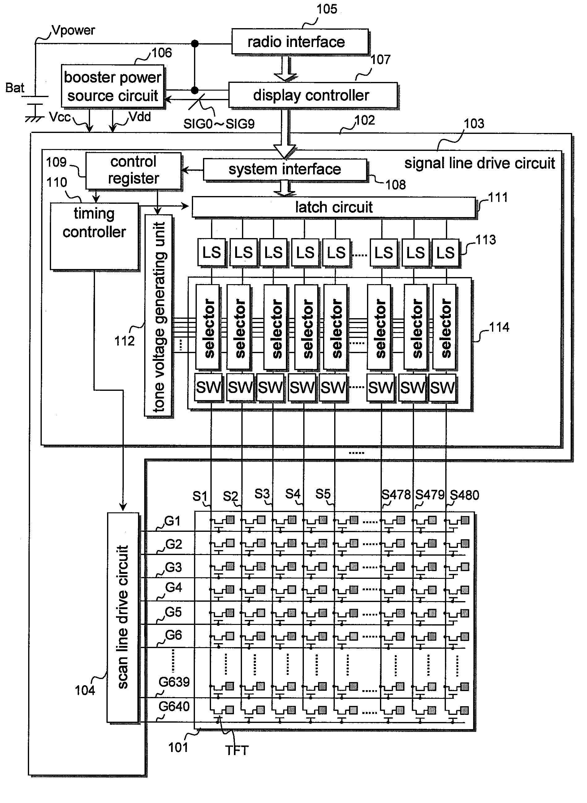
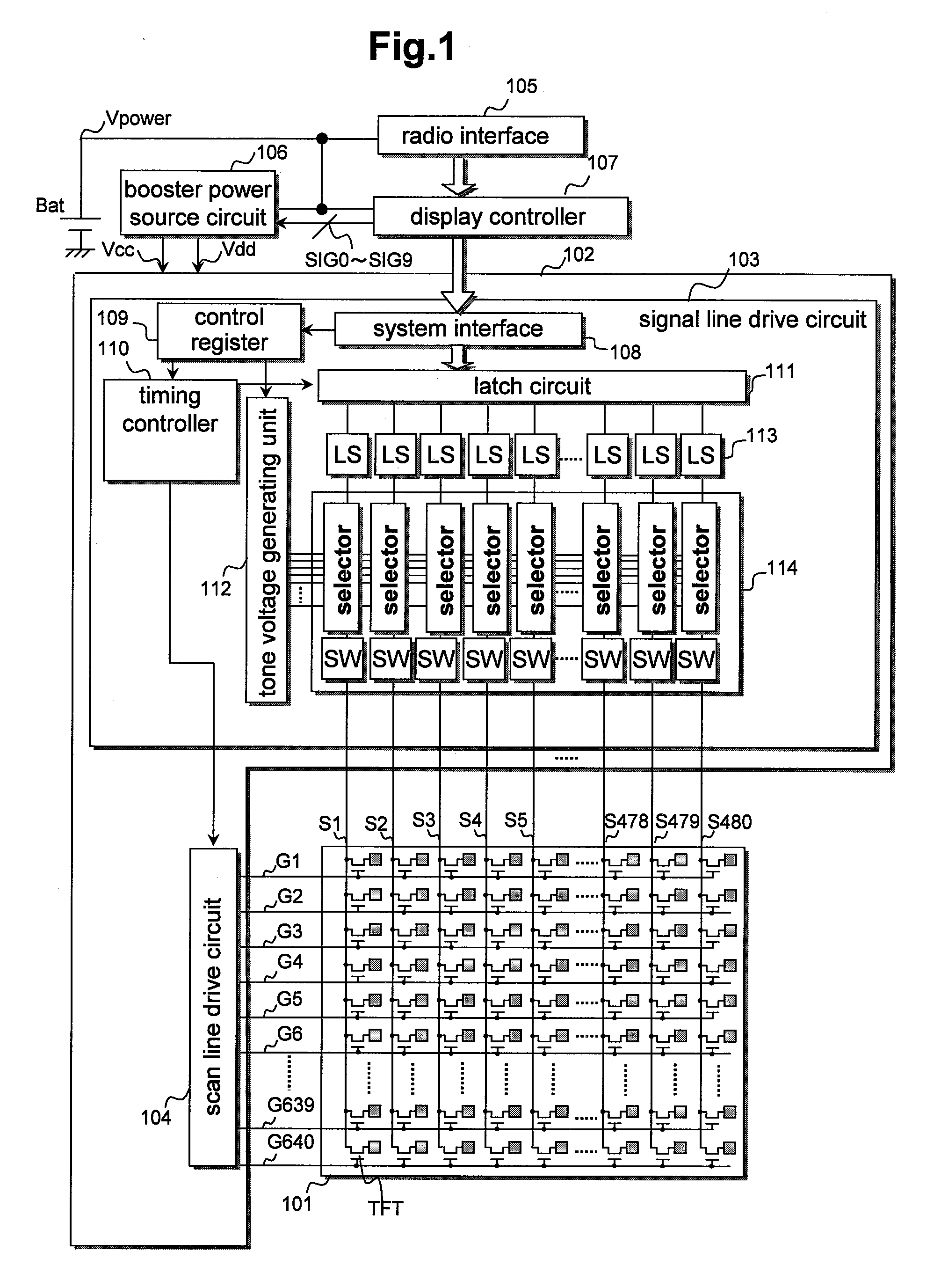
[1] An electronic paper display as a typical embodiment of the present invention has an electronic paper display panel (101), a display driver / controller (102), a battery (Bat), and a booster power source circuit (106).

[0035]The electronic paper display panel (101) can display data by writing display data and, after the writing, can hold the display even in a no-power state (refer to FIG. 1).

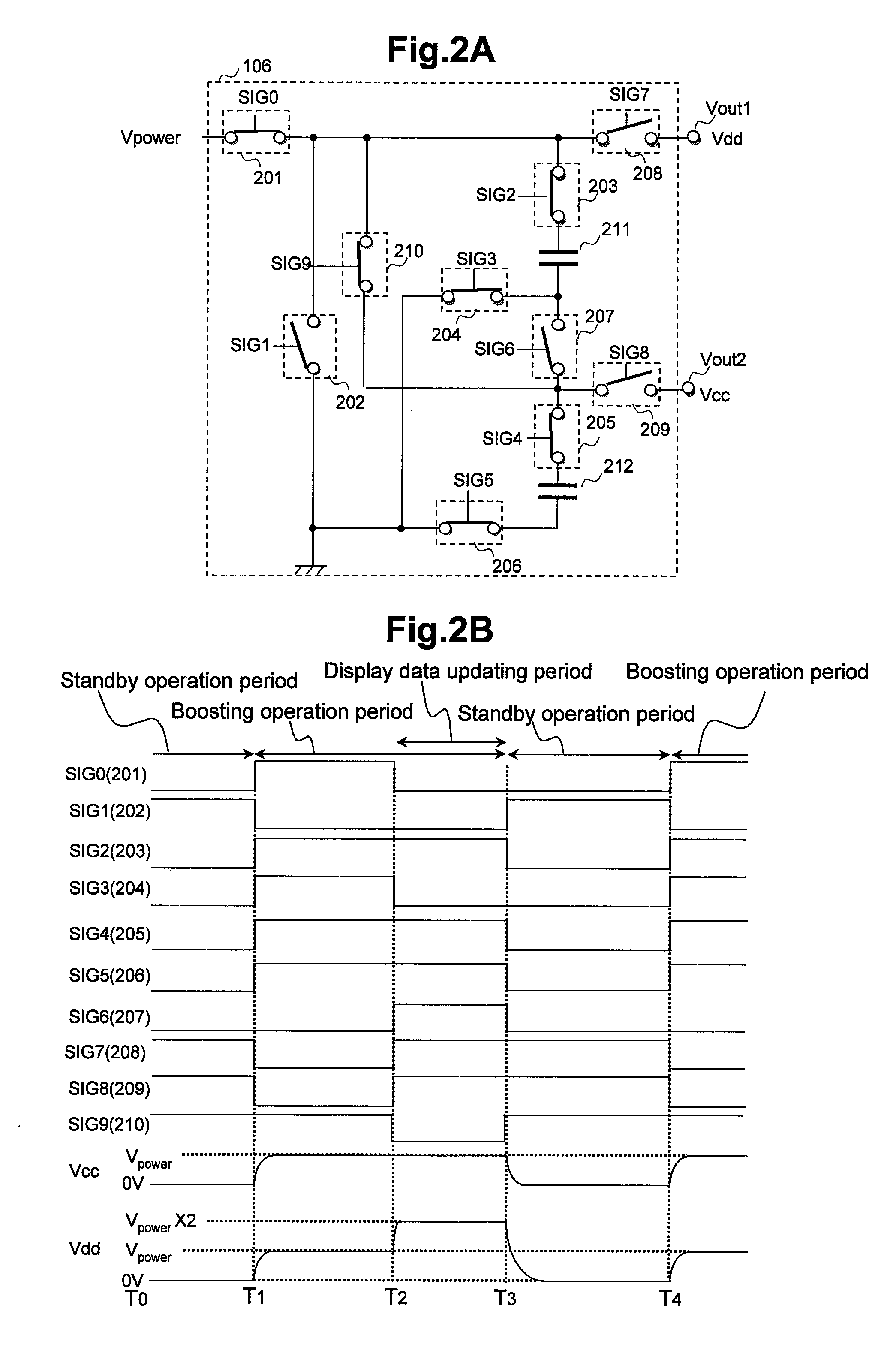
[0036]The booster power source circuit (106) generates a boosted power source voltage (Vdd) by an operation of boosting power source voltage (Vpower) supplied from the battery (Bat) (refer to a period from T1 to T2 and a period from T2 to T3 in FIG. 2B).

[0037]The display driver / con...


PUM


Abstract

The present invention is directed to reduce power consumption in a standby operation period as a period of holding display in a no-power state. An electronic paper display has an electronic paper display panel, a display driver / controller, a battery, and a booster power source circuit. The display panel can display data by writing display data and, after that, can hold the display in a no-power state. The booster power source circuit generates a boosted power source voltage by an operation of boosting power source voltage from the battery, and the display driver / controller executes the writing of the displayed data to the display panel by using the boosted power source voltage. In the following standby operation period in which the display panel holds the display in the no-power state, the boosting operation of the booster power source circuit is stopped.

Description

CLAIM OF PRIORITY[0001]The present application claims priority from Japanese application JP 2008-184385 filed on Jul. 16, 2008, the content of which is hereby incorporated by reference into this application.BACKGROUND OF THE INVENTION[0002]The present invention relates to an electronic paper display, a semiconductor integrated circuit for use in the same, and an operation method for the semiconductor integrated circuit. More particularly, the invention relates to a technique useful to reduce power consumption in a standby operation period as a period of holding display in a no-power state.[0003]Non-patent document 1 describes a 3.8-inch QVGA (320×240 pixels) color electronic paper capable of maintaining display even when the power source is turned off, having high reflectance of 30%, capable of performing light color display of 4,096 colors, and having a small thickness of 0.8 mm. Since no power is necessary to maintain display and rewriting is performed with low power consumption, ...

Claims


Application Information

Patent Timeline
Patent Type & Authority Applications(United States)
IPC IPC(8): G06F3/038
CPCG06F3/147G09G3/2092G09G3/3651G09G3/3688G09G3/3696G09G2380/14G09G2330/022G09G2370/16G09G2380/02G09G2380/04G09G2310/0289G09G3/035
Inventor AKAI, AKIHITONITTA, HIROYUKI
Owner RENESAS ELECTRONICS CORP
Why Eureka
Try Eureka