Pin definition layout of electronic paper display screen

a technology of electronic paper and display screen, applied in the field of electronic paper, can solve the problems that the lcd cannot replace newspapers and magazines, and achieve the effects of reducing the complexity of wires, reducing interference between pins, and improving circuit stability

Active Publication Date: 2010-01-21
E INK HLDG INC
View PDF7 Cites 14 Cited by
  • Summary
  • Abstract
  • Description
  • Claims
  • Application Information

AI Technical Summary

Benefits of technology

[0014]The present invention is directed to a pin definition layout of electronic paper display screen, which is capable of reducing the interference between pins, reducing the wire complexity, improving the circuit stability, achieving preferred electrical properties, and being more advantageous to the demand of “light, thin, short, and small”.
[0015]As embodied and broadly described herein, the pin definition layout of electronic paper display screen as described in the present invention has an electronic paper. The electronic paper has a plurality of pins for electrical connection. The pins are at least divided into a first pin area, a data signal source driver area, and a second pin area. Thus, during the manufacturing process of the electronic paper, pin layout is merely required to be performed at one side, which reduces the wire complexity, the area, and the number of the pins.
[0016]The data signal source driver area is provided with a plurality of data signal source drivers for inputting external signals. The first and the second pin areas respectively have a first and a second power supply pin set, a first and a second logic pin set disposed therein. A NO connection is disposed between each two pins in the first and the power supply pin sets, and thus when the external power supply is input to the electronic paper through the first and the second power supply pin set, the pins are separated by the NO connections to avoid interference there-between.

Problems solved by technology

Many information must be stored into a computer or PDA, and then displayed on LCD when reading, so LCD can not replace newspapers and magazines.

Method used


Image

  • Pin definition layout of electronic paper display screen
  • Pin definition layout of electronic paper display screen
  • Pin definition layout of electronic paper display screen

Examples


Embodiment Construction

[0025]In order to make the examiners to understand the disclosure of the present invention clearly, the present invention is illustrated with reference to the drawings.

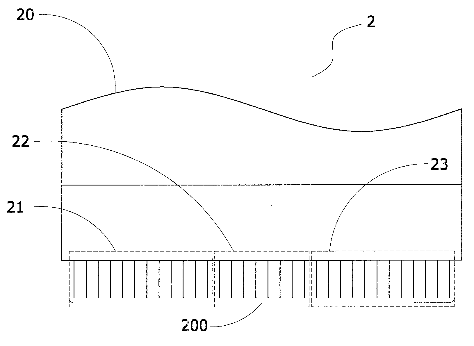
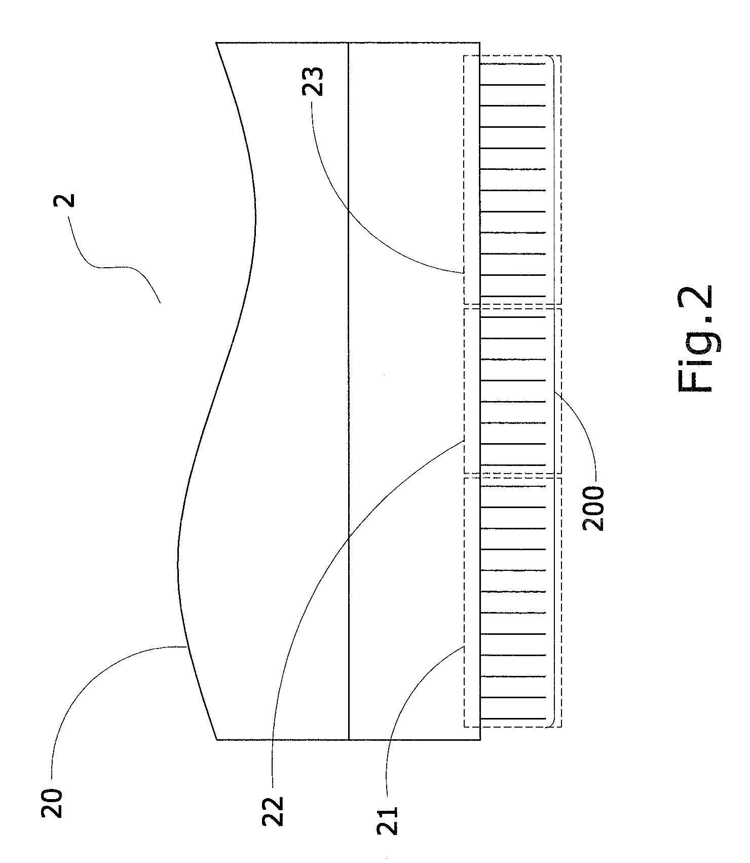
[0026]FIGS. 2 and 3 are a block diagram and a schematic view of pins of a preferred embodiment of the present invention. Referring to FIGS. 2 and 3, the pin definition layout of electronic paper display screen according to the present invention mainly has an electronic paper 2 having a plurality of pins 200 disposed at any side thereof. The pins 200 are divided into a first pin area 21, a data signal source driver area 22, and a second pin area 23 in sequence.

[0027]The first pin area 21 has a first power supply pin set 210 and a first logic pin set 211.

[0028]The first power supply pin set 210 has a negative power supply 2101 for inputting external negative potential, a positive power supply 2102 for inputting external positive potential, and a ground 2103 for grounding. The negative power supply 2101, the positive pow...


PUM


Abstract

A pin definition layout of electronic paper display screen is provided. The electronic paper has a first pin area, a data signal source driver area, and a second pin area sequentially disposed at any side thereof. The first pin area and the second pin area each have a first power supply pin set and a second power supply pin set disposed thereon, and a plurality of No connections is disposed by intervals in the first power supply pin set and the second power supply pin set, so as to separate potential pins. Therefore, no interference is generated between the pins, thus achieving good electrical properties and reducing the wire complexity.

Description

BACKGROUND OF THE INVENTION[0001]1. Field of the Invention[0002]The present invention relates to an electronic paper, and in particularly, to a pin definition layout of electronic paper display screen having good electrical output properties and high yield after definition arrangement of pins, which is advantageous in being light, thin, short, and small.[0003]2. Related Art[0004]Generally speaking, liquid crystal display (LCD) is most used in 3C products. Many information must be stored into a computer or PDA, and then displayed on LCD when reading, so LCD can not replace newspapers and magazines. Therefore, a new generation display technique is an electronic paper display screen.[0005]The development of the electronic paper display screen technology substantially includes electronic display and paper media. The electronic display is mainly made to be further light and thin, and be an animation display having the main features such as high chromaticity, high definition, and high bri...

Claims


Application Information

Patent Timeline
Patent Type & Authority Applications(United States)
IPC IPC(8): H02B1/00
CPCG09G3/34G09G2310/0275G09G2310/0267G09G2300/0426
Inventor HSU, YU-CHENWU, CHI-MENGCHEN, YA-ROUCHANG, HENG-HAOCHIEN, CHUN-TAHUANG, CHIEN-PANGSU, CHENG-YI
Owner E INK HLDG INC
Why Eureka
Try Eureka