Electric storage unit
a technology of electric power storage and electric components, applied in secondary cells, battery/fuel cell control arrangement, battery components, etc., can solve the problems of reducing reliability, shortening the life of electric components, and air not necessarily cooling each electric, so as to reduce the variation of cooling of electric power storage elements and high reliability
- Summary
- Abstract
- Description
- Claims
- Application Information
AI Technical Summary
Benefits of technology
Problems solved by technology
Method used
Image
Examples
exemplary embodiment 1
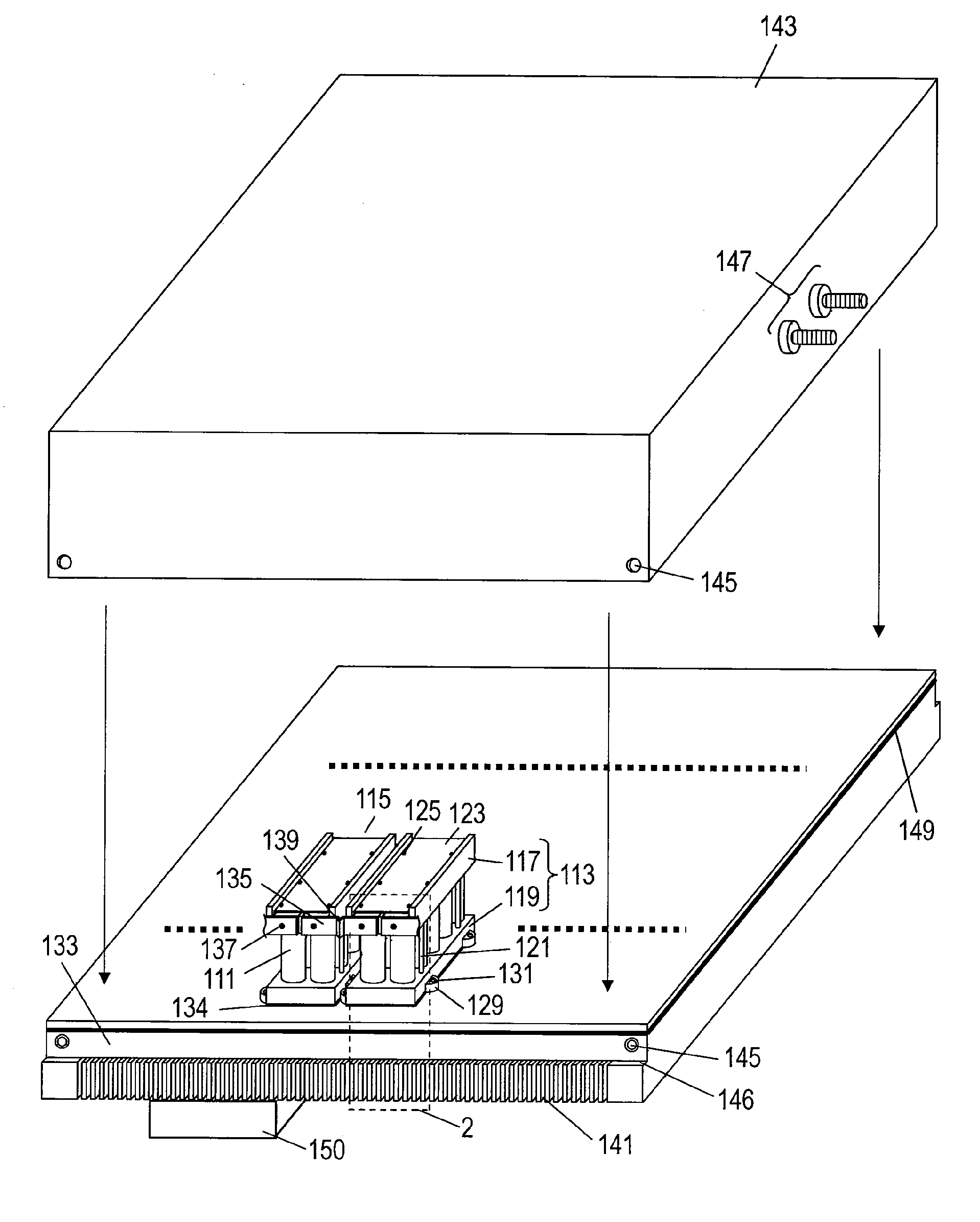
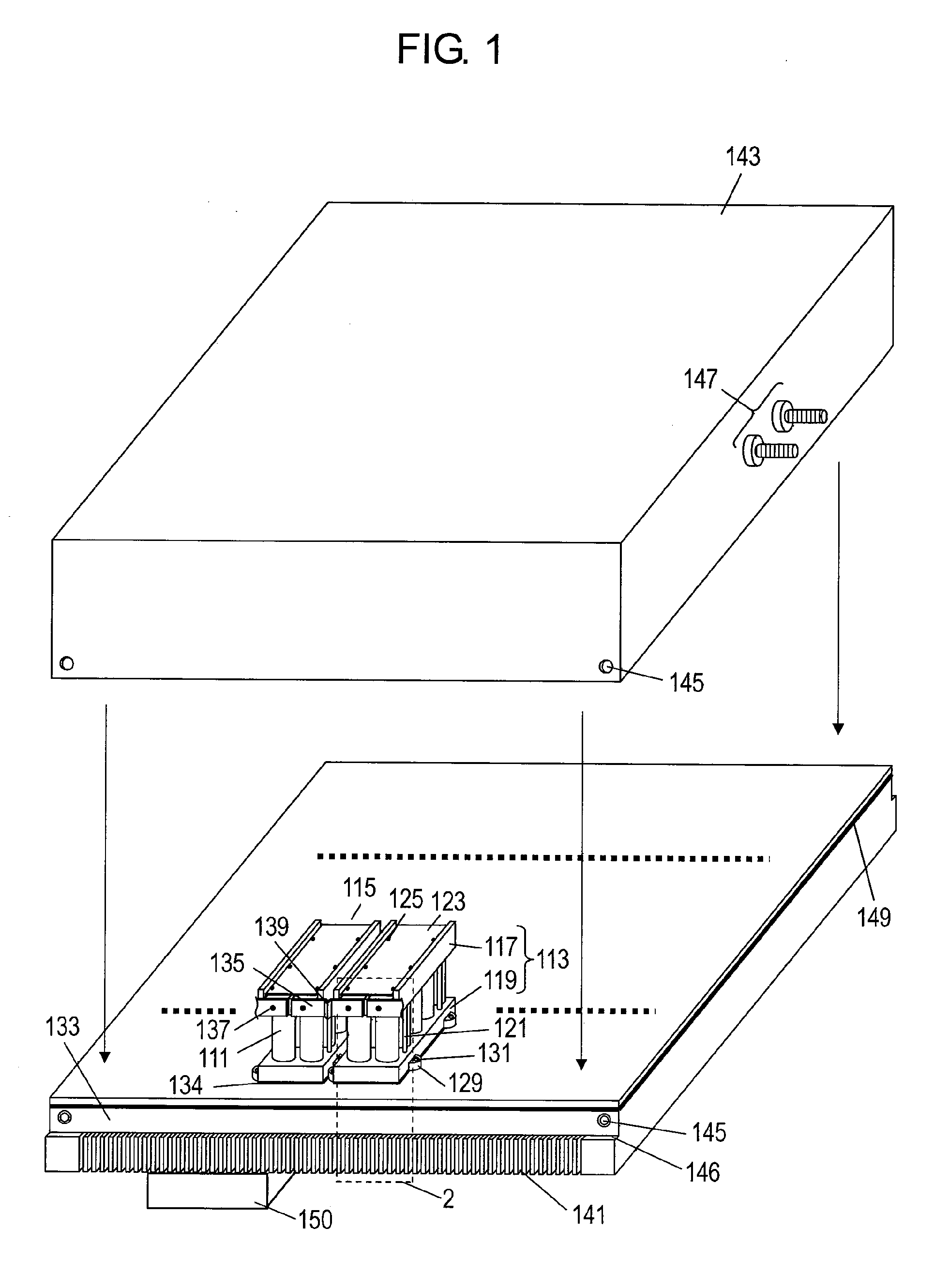
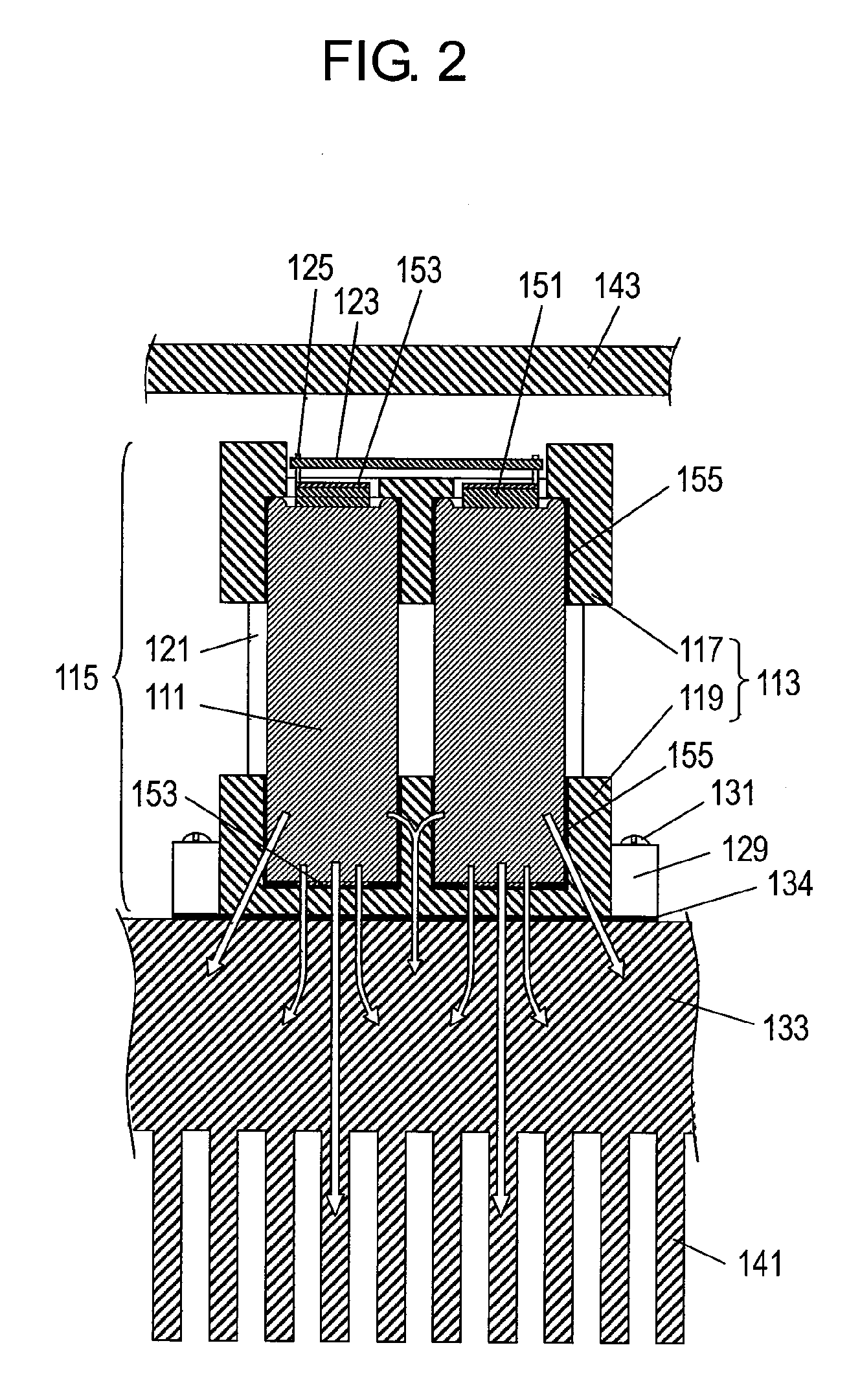
[0099]FIG. 1 is an exploded perspective view of an electric power storage unit according to Exemplary Embodiment 1 of the present invention. FIG. 2 is a cross sectional view of the electric power storage unit according to Embodiment 1.
[0100]As shown in FIG. 1, electric power storage element 111 is an electric double layer capacitor having a large capacitance operable to be charged and discharged quickly. However, the electric double layer capacitor has a low rated voltage of about 2.2V, and causes plural electric power storage elements 111 to be connected electrically in order to obtain a high rated voltage necessary for, e.g. driving a motor of a vehicle. In this case, plural storage element blocks 115 each including a predetermined number of electric power storage elements 111, e.g. ten elements according to Embodiment 1, and case 113 mechanically holding the elements.
[0101]Case 113 includes upper case 117 and lower case 119, and have respective both ends of ten electric power sto...
exemplary embodiment 2
[0119]FIG. 3 is an exploded perspective view of an electric power storage unit according to Exemplary Embodiment 2 of the present invention. FIG. 4 is a cross sectional view of the electric power storage unit according to Embodiment 2. In FIG. 3, components identical to those shown in FIG. 1 are denoted by the same reference numerals, and their detail description will be omitted.
[0120]The unit according to Embodiment 2 has the following features:
[0121](1) Heat-conductive elastic materials 157 made of elastic material, such as rubber, containing heat-conductive material, such as metal or carbon, are provided on portions of an upper surface of upper case 117 at both sides of upper case 117 in a longitudinal direction of circuit board 123; and
[0122](2) At least a part of the top surface of upper case 117 contacts cover 143 via heat-conductive elastic material 157 when cover 143 is placed on base 133. In other words, cover 143 and the top surface of upper case 117 faces each other acros...
exemplary embodiment 3
[0131]FIG. 5 is an exploded perspective view of an electric power storage unit according to Exemplary Embodiment 3 of the present invention. FIG. 6 is a cross sectional view of the electric power storage unit according to Embodiment 3. In FIG. 5, components identical to those shown in FIG. 3 are denoted by the same reference numerals, and their detail description will be omitted. Storage element block 115 has the same structure as that of Embodiment 2, and the reference numerals denoting the detail structure of block 115 will be omitted.
[0132]According to Embodiment 3, cooling-water passage 161 is formed inside base 133. Cooling water containing antifreeze solution circulates in cooling-water passage 161 to increase cooling efficiency. Cooling-water passage 161 is provided in base 133 and faces bottom surfaces of storage element blocks 115. In other words, cooling-water passage 161 is located directly under the bottom surfaces of individual storage element blocks 115. Cooling-water ...
PUM
 Abstract
Description
Claims
Application Information
 - R&D
- Intellectual Property
- Life Sciences
- Materials
- Tech Scout
- Unparalleled Data Quality
- Higher Quality Content
- 60% Fewer Hallucinations
Browse by: Latest US Patents, China's latest patents, Technical Efficacy Thesaurus, Application Domain, Technology Topic, Popular Technical Reports.
© 2025 PatSnap. All rights reserved.Legal|Privacy policy|Modern Slavery Act Transparency Statement|Sitemap|About US| Contact US: help@patsnap.com


