Method for Manufacturing Micro-Hinge Used in Electric Devices

a technology of electric devices and micro-hinges, which is applied in the direction of manufacturing tools, electric apparatus casings/cabinets/drawers, wing accessories, etc., can solve the problems of insufficient quality and durability, poor accuracy, and insufficient damping to achieve consistent damping, improve accuracy, and improve durability

Inactive Publication Date: 2010-01-28
HUANG KUO HUA
View PDF1 Cites 12 Cited by
  • Summary
  • Abstract
  • Description
  • Claims
  • Application Information

AI Technical Summary

Benefits of technology

[0006]A primary object of the invention is to provide a method for manufacturing a micro-hinge, which simplifies procedure and impr

Problems solved by technology

The sleeve 2 is formed by bending, so its accuracy is not good enough to generat

Method used


Image

  • Method for Manufacturing Micro-Hinge Used in Electric Devices
  • Method for Manufacturing Micro-Hinge Used in Electric Devices
  • Method for Manufacturing Micro-Hinge Used in Electric Devices

Examples


first embodiment

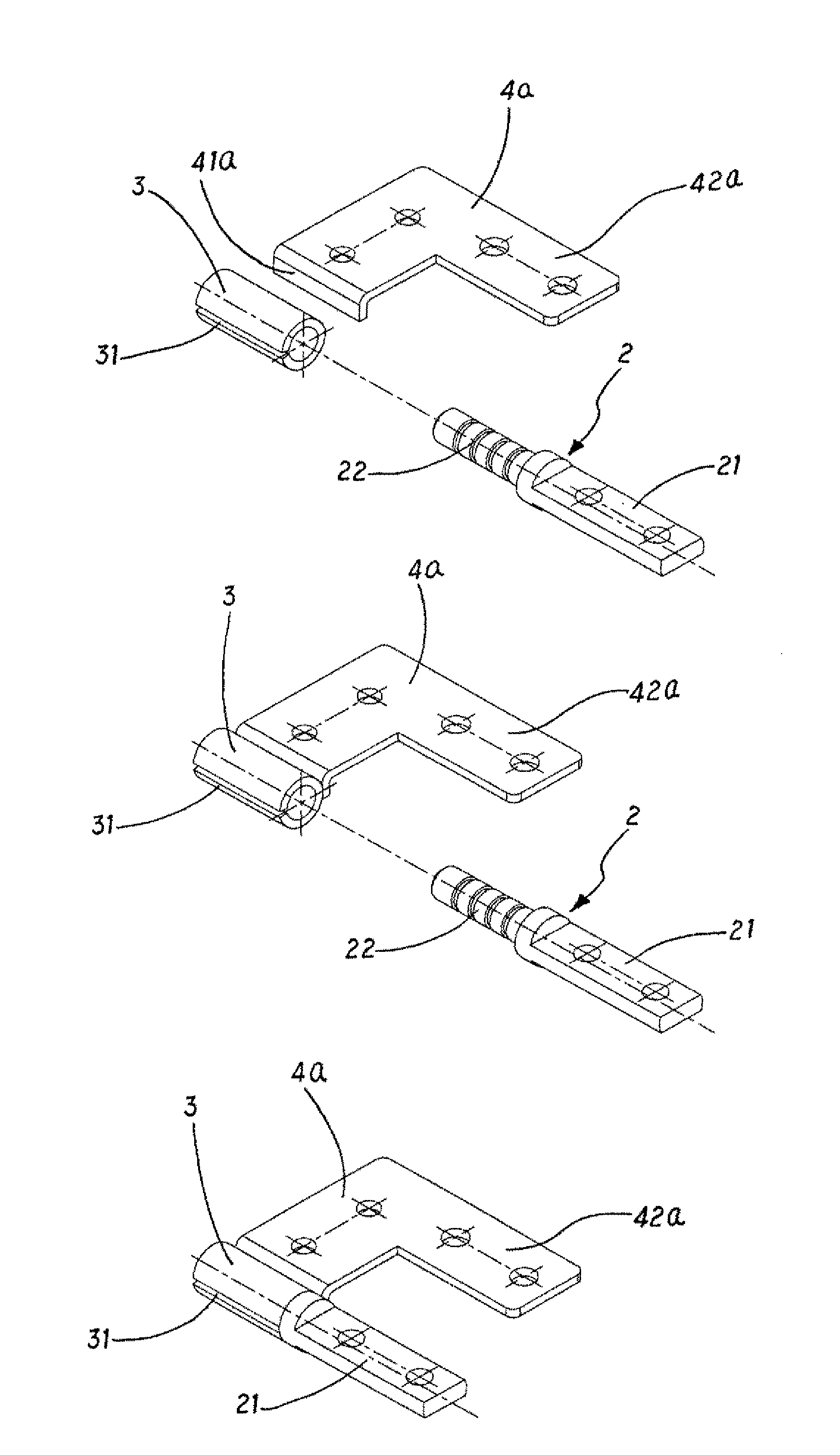
[0022]FIGS. 3 and 4 illustrate the invention. The invention provides a method for manufacturing a micro-hinge pivoting two pieces of an electric device. The method includes the steps of:

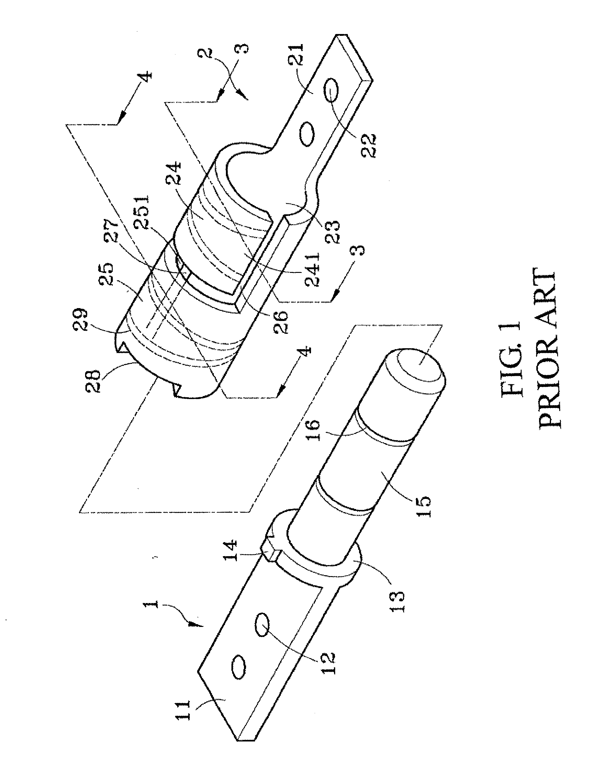
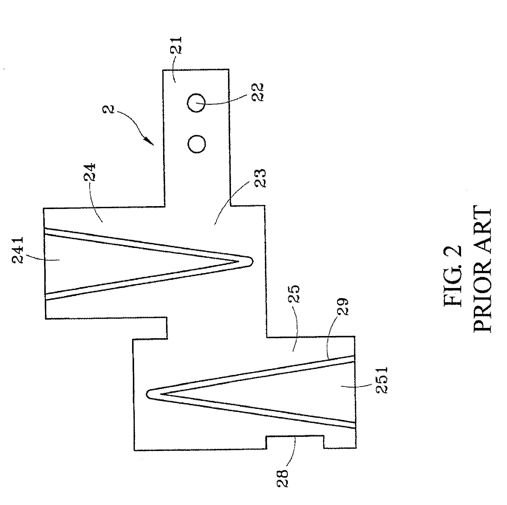
[0023]a) forming a shaft 2 having a mounting end 21 and a rotating portion 22, wherein the mounting end 21 has at least one shaft hole 210 for being passed through by a fastener (not shown) to connect an object T1, and a round block 211 between the mounting end 21 and rotating portion 22, wherein a diameter of the rotating portion 22 is smaller than that of the round block 211, and the rotating portion is provided with a plurality of oil troughs 221 on its surface;

[0024]b) forming a sleeve 3 having a slot 31 and an inner diameter slightly smaller than an outer diameter of the rotating portion 22;

[0025]c) providing a connecting element 4 being an L shaped plate and having an connecting end 41 and an extending end 42, wherein the extending end 42 has at least one through hole 421 for being passed throu...

third embodiment

[0029]FIG. 6 illustrates the invention. In this embodiment, the connecting element 4b is formed into a T shaped plate having a connecting end 41b for connecting the sleeve 3 and an extending end 42b. The sleeve 3 is fixed on the connecting end of the connecting element 4b by soldering.

fourth embodiment

[0030]FIG. 7 illustrates the invention. In this embodiment, the connecting element 5 has a tubular connecting end 51 and an extending end 52. The tubular connecting end 51 tightly sheathes the sleeve 3. The rotating portion 22 is inserted into the sleeve 3 to form a hinge with damping. As shown in FIG. 8, the mounting end 21 of the shaft 2 and the extending end 52 of the connecting element 5 are fixed at the objects T1 and T2, respectively. Therefore, the two objects T1 and T2 can be rotated to open or close.


PUM

PropertyMeasurementUnit
Shapeaaaaaaaaaa

Abstract

A method for manufacturing a micro-hinge pivoting two pieces of an electric device is disclosed. The method includes the steps of: a) forming a shaft having a mounting end and a rotating portion and a round block between the mounting end and rotating portion; b) forming a sleeve having a slot and an inner diameter slightly smaller than an outer diameter of the rotating portion; c) providing a connecting element having an connecting end and an extending end; d) combining the connecting end and sleeve; and e) inserting the rotating portion into the sleeve.

Description

[0001]The present invention is a continuation-in-part of U.S. patent application Ser. No. 11 / 448,655 filed on Jun. 8, 2006.BACKGROUND OF THE INVENTION[0002]1. Technical Field[0003]The invention relates to pivoting mechanisms for openable devices.[0004]2. Related Art[0005]Many electric devices, such as laptop computers, LCDs, cellular phones and electronic dictionaries, use pivots to make two pieces openable or rotary. USPAP 2003 / 0126719 discloses a typical prior art shown in FIGS. 1 and 2. '719 is composed of a shaft 1 and a sleeve 2. The shaft 1 is provided with a mounting end 11, a hole 12, a disk 13, a protruding block 14, a shaft rod 15 and an oil groove 16. The shaft 2 is provided with a supporting end 11, a through hole 12, a shaft hole 23, a first and second elastic portion 24, 25 with respective open edges 241, 251, a first and second slot 26, 27, a limiting trough 28 and an inner surface 29. In the manufacturing process, the sleeve2 is formed into a flat plate first, and th...

Claims


Application Information

Patent Timeline
IPC IPC(8): B21D53/40E05D11/08B23P11/00
CPCE05D3/10E05D11/082E05Y2900/208Y10T29/4984Y10T16/54038Y10T29/24H05K5/0226
Inventor HUANG, KUO-HUA
Owner HUANG KUO HUA
Why Eureka
Try Eureka