Rack shaft support device and torsion amount adjustment method for torsion spring used therein

a torsion amount and torsion spring technology, which is applied in the direction of torsion springs, transportation and packaging, gearing, etc., can solve the problem of difficult torsion amount setting of torsion bar springs, and achieve the effect of preventing the occurrence of rattling sound and good accuracy

Active Publication Date: 2010-01-28
JTEKT CORP
View PDF8 Cites 24 Cited by
  • Summary
  • Abstract
  • Description
  • Claims
  • Application Information

AI Technical Summary

Benefits of technology

[0010]According to the above-described aspect, the torsion amount of the torsion spring can be adjusted with the torsion amount adjusting member that is attached to the sealing member in such a manner that a position of the torsion amount adjusting member with respect to the sealing member is adjustable. As a result, the torsional torque generated by the torsion spring can be controlled with good accuracy. Therefore, a spread in the pushing force in the meshing portion of the rack and pinion can be inhibited. As wear of the sliding portions of the rack shaft support member and rack shaft advances, the intermediate member is rotated by the torsion spring. As a result, the intermediate member pushes the rack shaft support member toward the rack shaft by the movement of the cam mechanism, thereby making it possible to maintain a substantially constant pushing force in the meshing portion of the rack shaft and pinion.
[0012]In this case, by operating the operation portion of the first end portion of the adjustment screw from the outside of the sealing member and adjusting the screwing position of the adjustment screw with respect to the threaded hole of the sealing member, it is possible to rotate also the other end portion of the torsion spring that is coupled to the coupling portion of the second end portion of the adjustment screw. As a result, the torsion amount of the torsion spring can be adjusted with good accuracy from the outside of the sealing member.
[0014]In this case, the end portions of the torsion coil spring that are perpendicular to the coil central axial line are mated with the coupling grooves of the adjustment screw and intermediate member. Therefore, the torsion coil spring can be twisted, without tumbling, about the coil central axial line thereof. As a result, a spread of the torsional torque with respect to the torsion amount can be inhibited.
[0016]In this case, the intermediate member can be fixed with respect to the sealing member in the axial direction and rotation direction by using a fixing jig screwed in the threaded hole of the intermediate member through the fixing jig insertion hole of the sealing member. In this state, the torsion amount of the torsion spring can be adjusted with good accuracy by using the torsion amount adjusting member that is attached to the sealing member in such a manner that a position of the torsion amount adjusting member with respect to the sealing member is adjustable.
[0017]The above-described aspect may be applied to a steering apparatus for a vehicle in which a rack shaft is slidably supported by using the rack shaft support device. With this aspect, a steering apparatus for a vehicle can be attained in which the occurrence of rattling sound can be reliably prevented.

Problems solved by technology

The torsion spring is disposed in a gap between the first groove and the second groove, but the torsion amount of the torsion bar spring is difficult to set.

Method used


Image

  • Rack shaft support device and torsion amount adjustment method for torsion spring used therein
  • Rack shaft support device and torsion amount adjustment method for torsion spring used therein
  • Rack shaft support device and torsion amount adjustment method for torsion spring used therein

Examples


Embodiment Construction

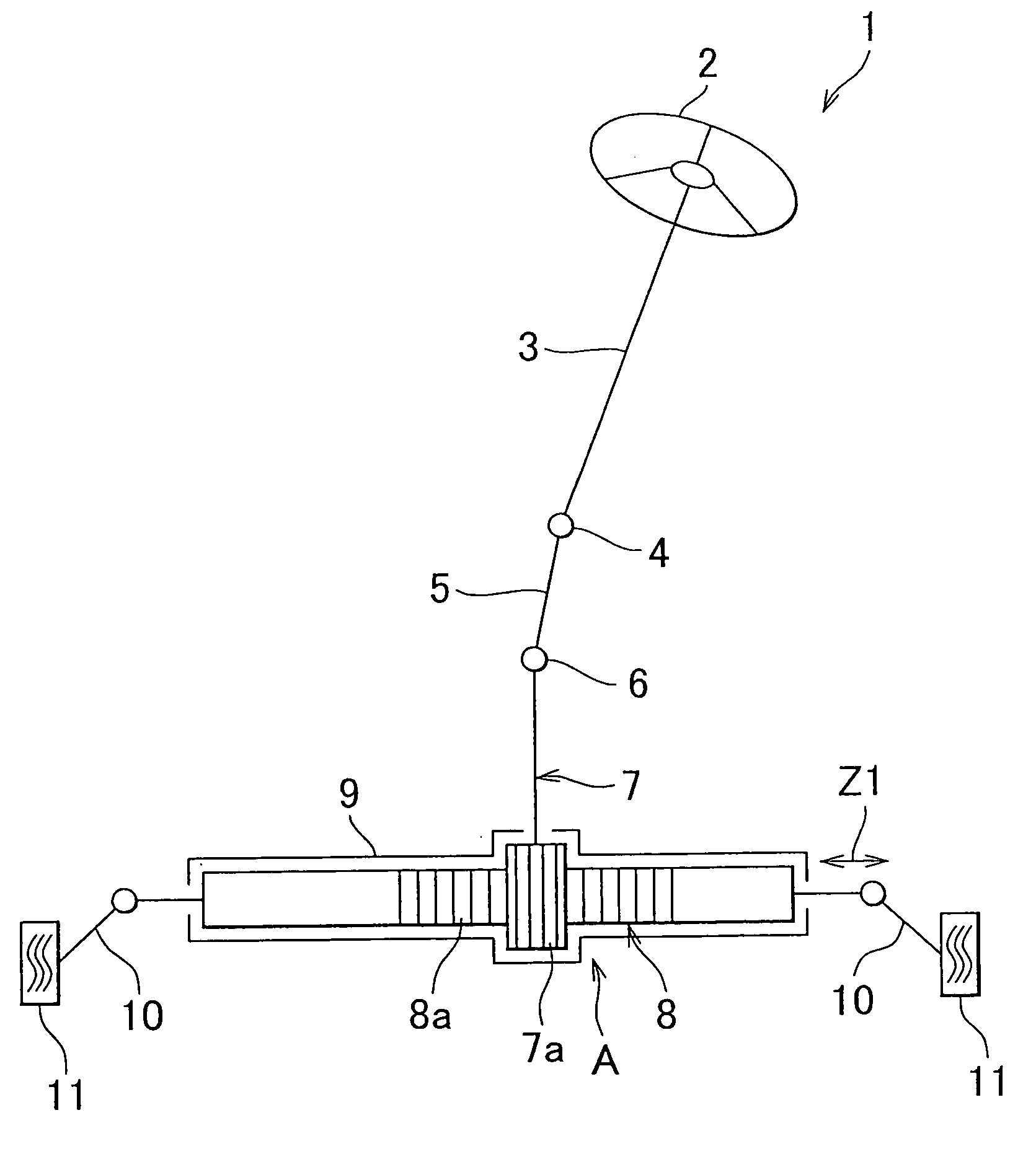
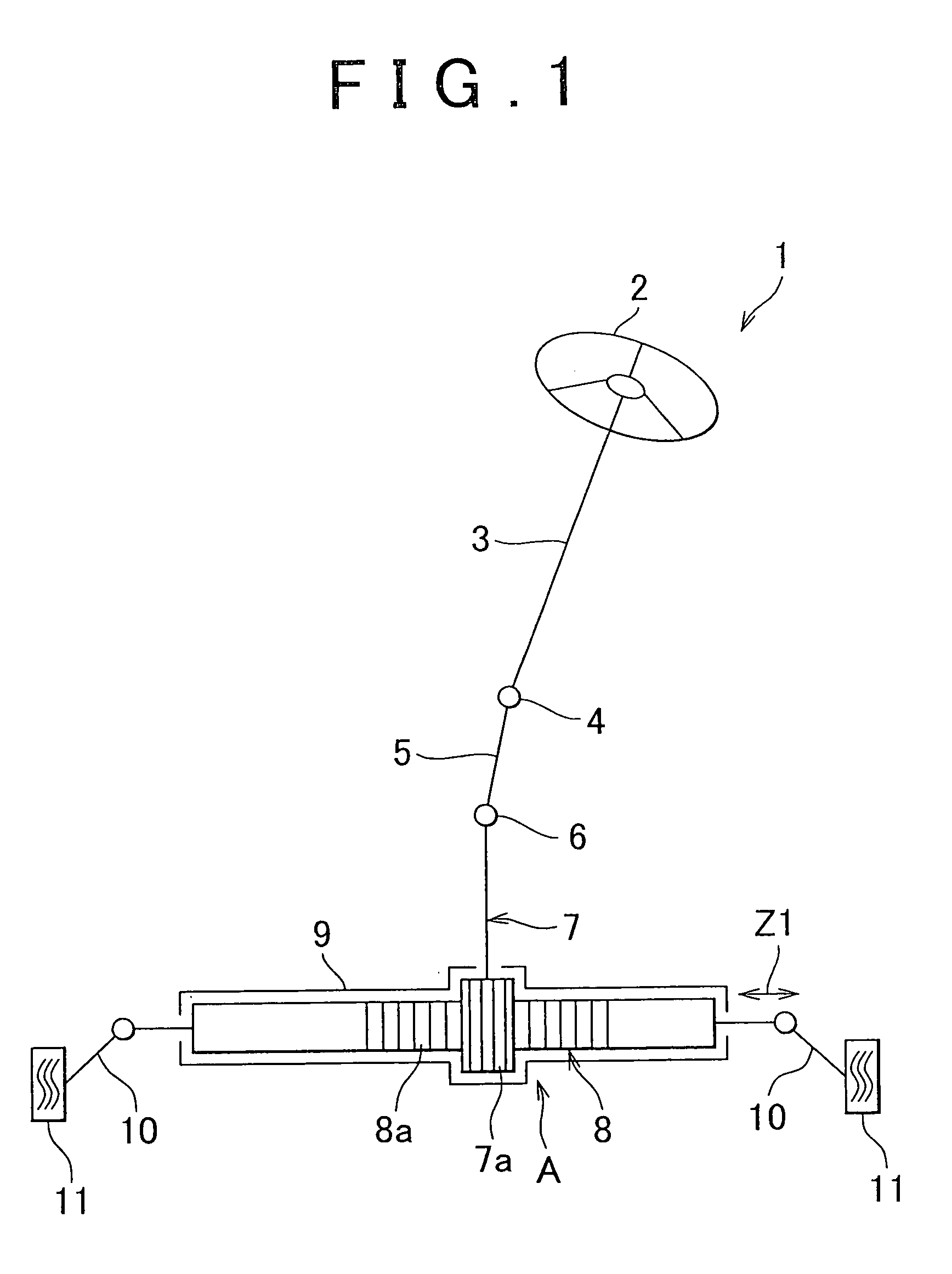
[0031]An embodiment of the invention will be described below with reference to the appended drawings. Referring to FIG. 1, a steering apparatus 1 for a vehicle includes a steering shaft 3 that is coupled to a steering member 2 such as a steering wheel, an intermediate shaft 5 that is coupled via a universal joint 4 to the steering shaft 3, a pinion shaft 7 that is coupled via a universal joint 6 to the intermediate shaft 5, and a rack shaft 8 that has a rack 8a that meshes with a pinion 7a provided in the vicinity of the end portion of the pinion shaft 7 and serves as a steering shaft extending in the transverse direction of an automobile. A rack-and-pinion mechanism A serving as a steering mechanism is constituted by the pinion shaft 7 and rack shaft 8.

[0032]The rack shaft 8 is supported, so that it can reciprocate linearly along an axial direction Z1, by a plurality of bearings (not shown in the figure) inside a rack housing 9 that is fixed to the vehicle body. Both end portions o...


PUM


Abstract

A rack shaft support device includes: a rack shaft support member that slidably supports a rack shaft; a sealing member fixed to an inlet port of a retention hole formed in a housing; an intermediate member that is interposed between the rack shaft support member and the sealing member; a torsion spring that couples the intermediate member so that torque is transmitted to the intermediate member; a torsion amount adjusting member that is attached to the sealing member in such a manner that a position of the torsion amount adjusting member with respect to the sealing member is adjustable and adjusts a torsion amount of the torsion spring; and a cam mechanism that converts a rotation force of the intermediate member induced by untwisting of the torsion spring into a force by which the intermediate member pushes the rack shaft support member.

Description

INCORPORATION BY REFERENCE[0001]The disclosure of Japanese Patent Application No. 2008-190205 filed on Jul. 23, 2008 including the specification drawings and abstract is incorporated herein by reference in its entirety.BACKGROUND OF THE INVENTION[0002]1. Field of the Invention[0003]The invention relates to a rack shaft support device and a method for adjusting a torsion amount of a torsion spring that is used therein.[0004]2. Description of the Related Art[0005]A steering apparatus of a rack-and-pinion system is usually provided with a rack shaft support device for removing backlash between the rack and the pinion. In the rack shaft support device, a support yoke that can slide back and forth and a compression coil spring that biases the support yoke are accommodated in a retention hole provided in a housing. By the support yoke biased by the compression coil spring, the rack shaft is axially slidably supported and also the rack shaft is pushed toward the pinion shaft.[0006]However,...

Claims


Application Information

Patent Timeline
Patent Type & Authority Applications(United States)
IPC IPC(8): B62D3/12F16F1/16
CPCB62D3/123Y10T74/1967F16H55/283
Inventor KAWAKUBO, AKITAKESUZUKI, YOSHINORIISHIMI, HIROFUMI
Owner JTEKT CORP
Why Eureka
Try Eureka