Efficient joint for vehicle energy-absorbing device

a technology of energy-absorbing devices and joints, which is applied in the direction of vehicle components, bumpers, vehicular safety arrangements, etc., can solve the problems of occupying packaging space in the vehicle, the plate at the joint adds mass, etc., and achieves accurate prediction of where the deformation occurs

Inactive Publication Date: 2010-01-28
GM GLOBAL TECH OPERATIONS LLC
View PDF14 Cites 33 Cited by
  • Summary
  • Abstract
  • Description
  • Claims
  • Application Information

AI Technical Summary

Benefits of technology

[0005]The energy-absorbing device may include first, second and third portions. The second portion may be oriented approximately perpendicularly with respect to the first and the third portions. The third portion of the energy-absorbing device may abut the inner rail surface. The energy-absorbing device may include at least one indentation configured to aid in an efficient longitudinal crush. The indentations serve to weaken the crush can at the site of the indentations, to enable an accurate prediction of where the deformation will occur during an impact event.
[0006]A bulkhead may be placed inside a cavity defined by the energy-absorbing device. The bulkhead prevents the crush c

Problems solved by technology

The presence of plates at the joint adds mass

Method used


Image

  • Efficient joint for vehicle energy-absorbing device
  • Efficient joint for vehicle energy-absorbing device
  • Efficient joint for vehicle energy-absorbing device

Examples


second embodiment

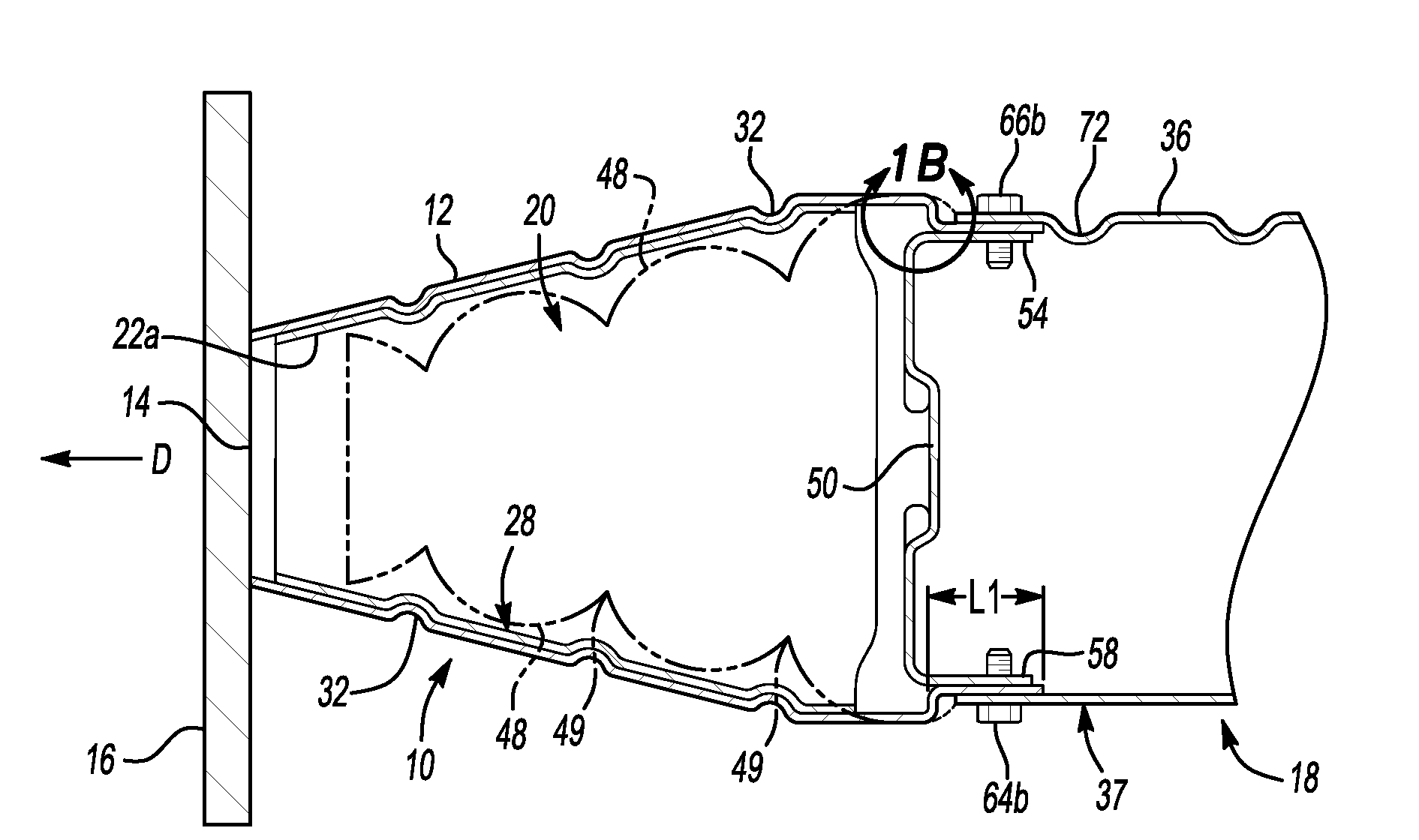
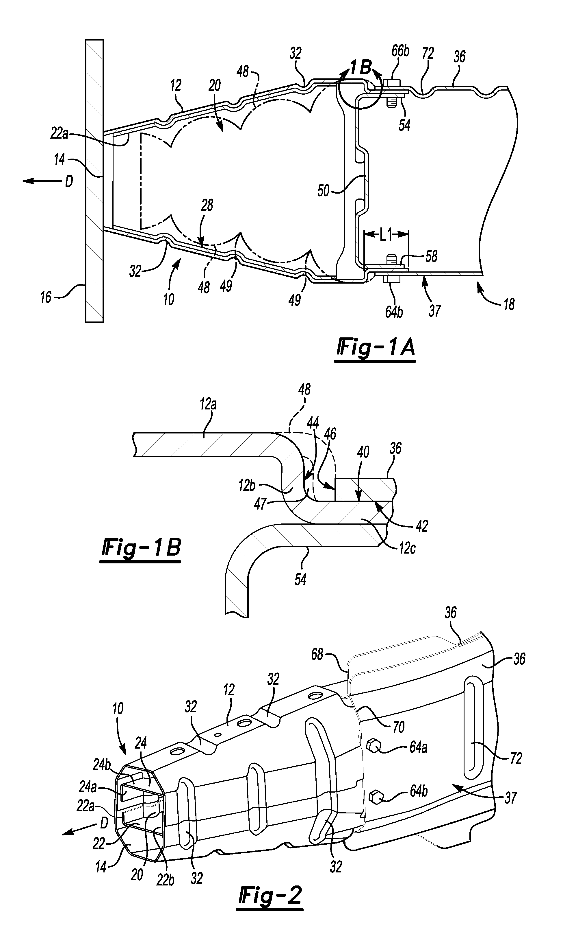
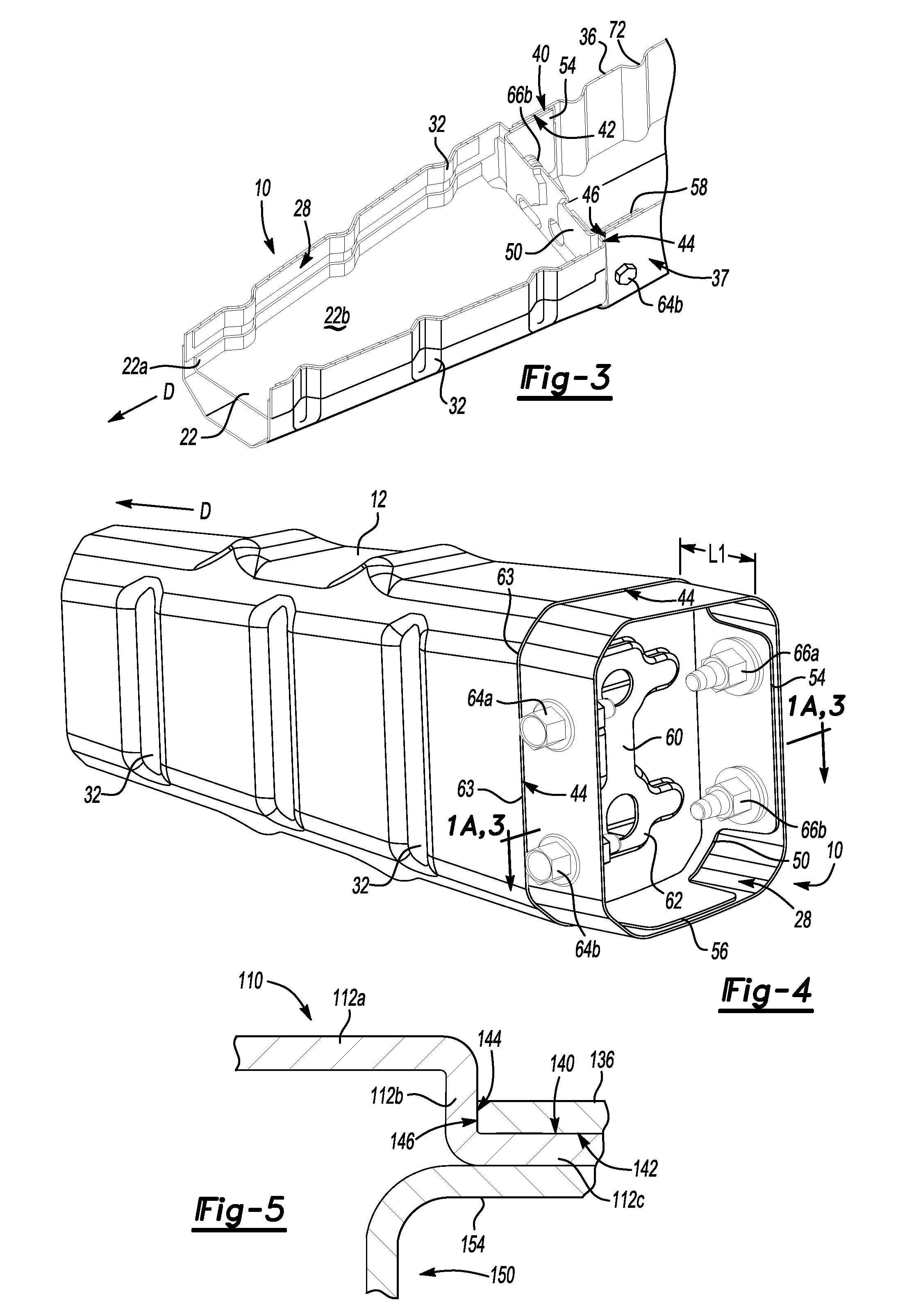
[0031]A second embodiment is shown in FIG. 5, with a crush can 110. FIG. 5 shows the same view as FIG. 1B, which is an enlarged view of the portion 1B of FIG. 1A. In the second embodiment, a second crush surface 144 directly contacts an edge surface 146 of the motor compartment rail 136 with no gap therebetween. In the second embodiment, the profile of the crush can 110 would remain the same at the second crush surface 144 in the event of an impact, since the second crush surface 144 is already in direct contact with the edge surface 146 of the motor compartment rail 136. Thus the second crush surface 144 directly interfaces with the edge surface 146, both in the absence and presence of an impact event. The crush can 110 is configured to transmit load received from the impact directly to the edge surface 146 of the motor compartment rail 136 through the second crush surface 144. This results in an efficient joint for the crush can 110.

[0032]The first crush surface 140 of the crush c...


PUM


Abstract

A vehicle having an energy-absorbing device mountable to a bumper of the vehicle is provided. The energy-absorbing device is attached to a vehicle rail having an inner rail surface and an edge surface. The energy-absorbing device defines a first crush surface interfacing with the inner rail surface. In a first embodiment, the energy-absorbing device defines a second crush surface positioned to directly interface with the edge surface of the vehicle rail in the event of an impact. The energy-absorbing device is configured to transmit load received from the impact directly to the edge surface of the vehicle rail through the second crush surface. This results in an efficient joint for the energy-absorbing device.

Description

TECHNICAL FIELD[0001]The invention relates in general to a vehicle with an energy-absorbing device mountable to a bumper of a vehicle.BACKGROUND OF THE INVENTION[0002]An energy-absorbing device, sometimes referred to as a crush box, is sometimes attached to a vehicle bumper so that in the event of a low-speed impact event, the energy-absorbing device deforms longitudinally, confining the damage to the energy-absorbing device. A low-speed impact event generally occurs at a velocity of approximately 10 miles per hour or less. In some designs, the energy-absorbing device transfers the load from an impact through a plate welded onto the end of the energy-absorbing device to a plate welded onto the end of the motor compartment rail. The presence of plates at the joint adds mass and takes up packaging space in the vehicle.SUMMARY OF THE INVENTION[0003]A vehicle having an energy-absorbing device mountable to a bumper of the vehicle is provided. The energy-absorbing device is attached to a ...

Claims


Application Information

Patent Timeline
IPC IPC(8): B60R19/34B60R19/24
CPCB60R19/34
Inventor STEWART, BRYAN J.NAYAK, RAVIRAJ U.
Owner GM GLOBAL TECH OPERATIONS LLC
Why Eureka
Try Eureka