Battery monitoring system

a battery and monitoring system technology, applied in the field of battery monitoring systems, can solve problems such as problems such as difficulty in detecting current flow from batteries, and inability to accurately sense and report battery operating conditions

Inactive Publication Date: 2010-01-28
LEAR CORP
View PDF91 Cites 68 Cited by
  • Summary
  • Abstract
  • Description
  • Claims
  • Application Information

AI Technical Summary

Problems solved by technology

These forces may induce vibrations that can make it difficult to sense current flow from the battery in the even the vibrations disrupt an electrical connection between the battery post connector and electronics used to

Method used


Image

  • Battery monitoring system
  • Battery monitoring system
  • Battery monitoring system

Examples


Embodiment Construction

)

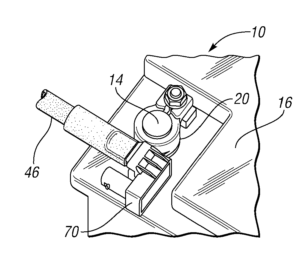
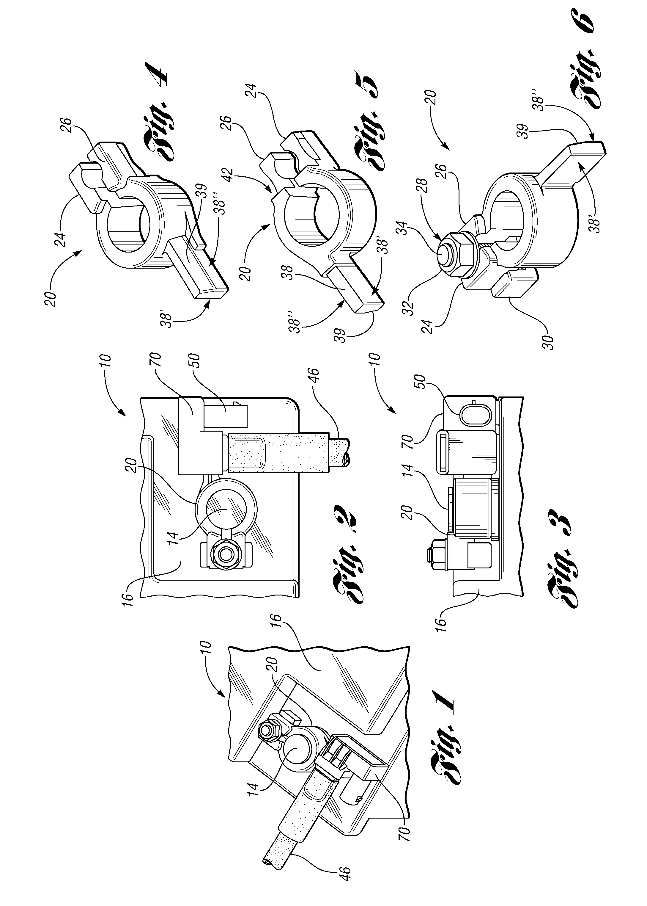
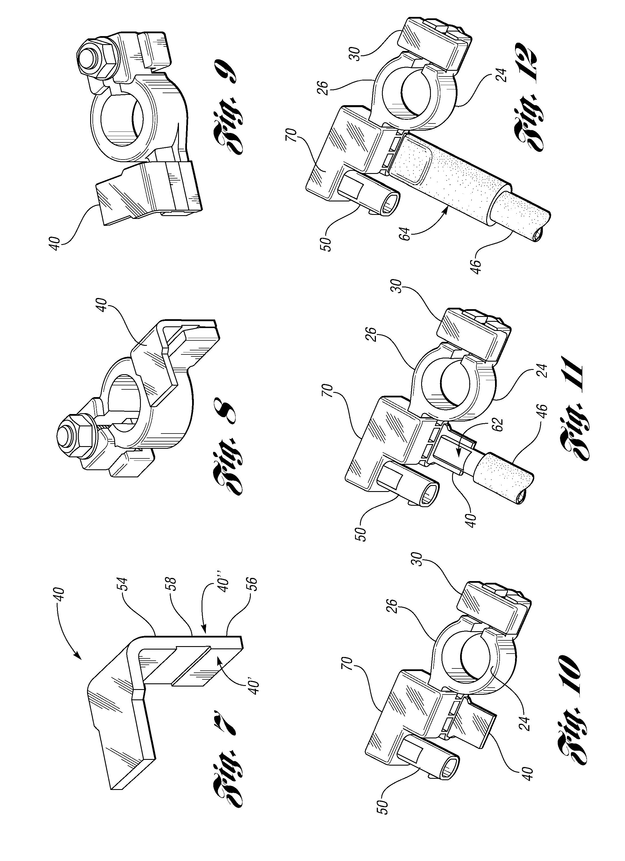
[0016]FIGS. 1-3 illustrate a battery monitoring system (BMS) 10 in accordance with one non-limiting aspect of the present invention. The BMS 10 may be connected to a battery post 14 of a battery 16, such as but not limited to a lead-acid or other energy storage / output device (capacitor, fuel cell, etc.) commonly employed within vehicles. The BMS 10 may be securely connected to the battery post 14 with compressive tightening of a terminal 20 or other suitable connection. The BMS 10 may be configured or otherwise programmed to support any number of operations, such as but not limited to measuring / sensing current, voltage, and temperatures associated with the battery 16.

[0017]The terminal 20 may comprise a tinned brass or other material suitable for conducting electricity from the battery post 14. The terminal 20 may be configured for attachment to a cylindrical, conical or other shaped battery post 14. FIGS. 4-6 illustrate the terminal being die-cast into a particular shape in accord...


PUM


Abstract

A battery monitoring system (BMS) configured for use in measuring operating conditions of a battery or other source of electric current. The BMS may include a housing configured to include a dampening element between a shunt and connection arm in order to limit the likelihood of vibrations and other forces acting on the BMS shorting or otherwise disrupting electrical connections used to measure current through the shunt.

Description

CROSS-REFERENCE TO RELATED APPLICATIONS[0001]This application claims the benefit of U.S. provisional application Ser. No. 61 / 135,691 filed Jul. 23, 2008.BACKGROUND OF THE INVENTION[0002]1. Field of the Invention[0003]The present invention relates to battery monitoring systems of the type that can be connected to a battery post to measure battery operating conditions.[0004]2. Background Art[0005]Hybrid and non-hybrid vehicles may be equipped with energy storage devices, such as batteries for powering the vehicle and other devices within the vehicle. A battery post connector may be connected to a battery post and configured to sense battery operating conditions. These types of connectors may be employed in automotive vehicles having lead-acid or some other type of battery or similar energy storage device in order to report battery operating conditions to a junction box or other vehicle system controller that may use the information for any number of purposes.[0006]Vehicles having batt...

Claims


Application Information

Patent Timeline
IPC IPC(8): H02J7/00
CPCG01R1/203G01R31/3606H01R11/287H01M10/48G01R31/3696G01R31/382G01R31/364Y02E60/10
Inventor RUBIO, JOSEP MARIA ROSET
Owner LEAR CORP
Why Eureka
Try Eureka