Liquid Crystal Display Device

Active Publication Date: 2010-01-28
PANASONIC LIQUID CRYSTAL DISPLAY CO LTD +1
View PDF3 Cites 19 Cited by
  • Summary
  • Abstract
  • Description
  • Claims
  • Application Information

AI Technical Summary

Benefits of technology

[0021]According to the invention, since a sealing material with which a TFT substrate and a counter substrate are bonded together is formed by screen printing, the time for the step of forming the sealing material can be greatly reduced. Accor

Problems solved by technology

It takes long to form a sealing material by using a dispenser.
In such a case, it takes very long to form the sealing material by using a dispenser.
Therefore, there arises a problem that the trace of the mesh is transferred to the alignment film to cause unevenness on screen.
In order to solve the mesh unevenness, a method for

Method used


Image

  • Liquid Crystal Display Device
  • Liquid Crystal Display Device
  • Liquid Crystal Display Device

Examples


Example

First Embodiment

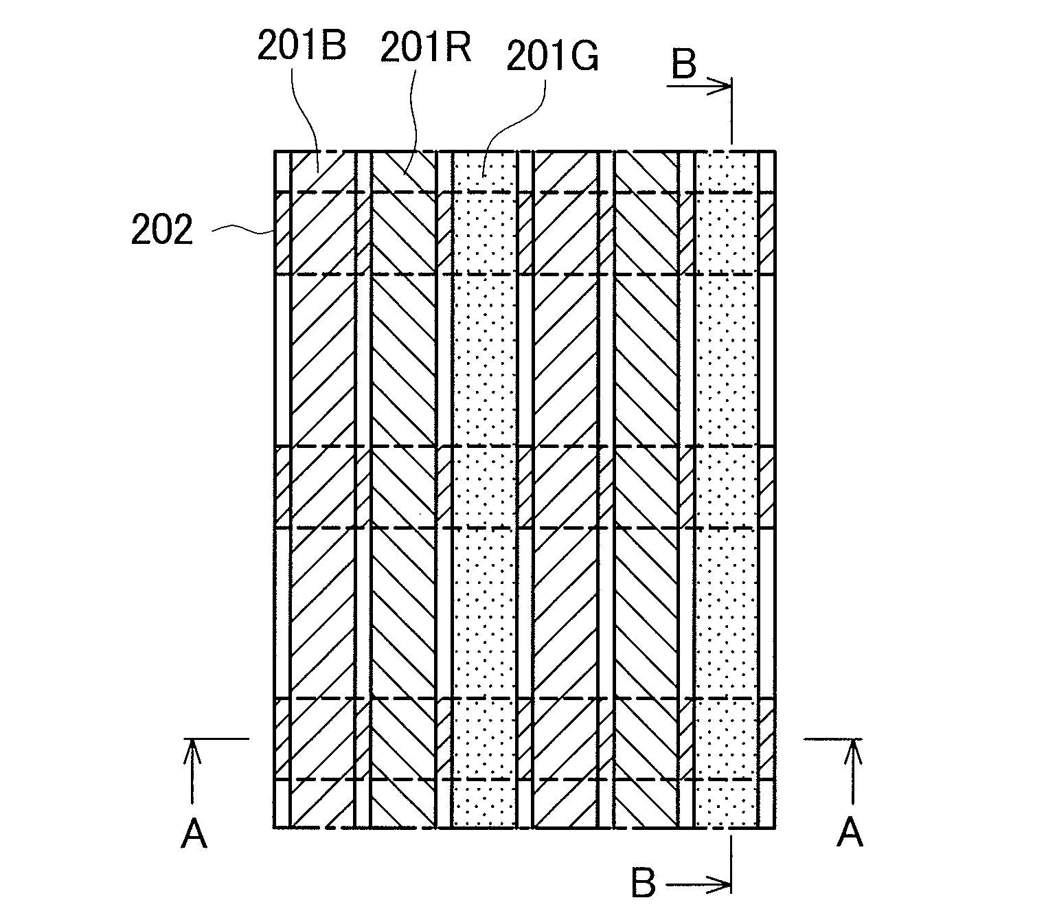
[0059]FIGS. 4A to 4C show the configuration of the display region 10 of the counter substrate 200, showing a first embodiment of the invention. FIG. 4A is a plan view of the pixel configuration of the display region 10. FIG. 4B is an A-A cross sectional view in FIG. 4A. FIG. 4C is a B-B cross sectional view in FIG. 4A. In FIG. 4A, the red color filters 201R, the blue color filters 201B, and the green color filters 201G extend in the vertical direction at predetermined intervals. In FIGS. 4A to 4C, the color filters 201 are formed in the order of the red color filter 201R, the blue color filter 201B, and the green color filter 201G.

[0060]The blue color filters 201B extend not only in the vertical direction but also in the horizontal direction so as to cover the light shielding films 202 which extend in the horizontal direction. Accordingly, the blue color filter 201B and the red color filter 201R, or the blue color filter 201B and the green color filter 201G are overl...

Example

Second Embodiment

[0075]FIGS. 7A to 7C show the pixel configuration of the counter substrate 200 showing a second embodiment of the invention. FIG. 7A is a plan view showing the configuration of the embodiment. FIG. 7B is an A-A cross sectional view in FIG. 7A. FIG. 7C is a B-B cross sectional view in FIG. 7A. In FIG. 7A, the red color filters 201R, the blue color filters 201B, and the green color filters 201G extend in the vertical direction. The respective color filters extend not only in the vertical direction but also in the horizontal direction at specific pitches. In FIG. 7A, only the green color filters 201G seem to extend also in the horizontal direction. However, also the blue color filters 201B and the red color filters 201R extend in the horizontal direction under the green color filters 201G. Although the light shielding films 202 extend in the horizontal direction at specific pitches, the light shielding films 202 are not shown in FIG. 7A because they are covered with th...


PUM


Abstract

Unevenness due to the influence of a mesh when a sealing material for bonding a TFT substrate and a counter substrate together is formed on the counter substrate by screen printing is prevented. Light shielding films are extended in the horizontal direction and arranged in the vertical direction. Red color filters, blue color filters, and green color filters are extended in the vertical direction at predetermined intervals. The blue color filters are extended also in the horizontal direction so as to cover the light shielding films. In a cross section along the red color filter and the green color filter, the level of a portion above the light shielding film is higher compared with that of the other portion by the thicknesses of the blue color filter and the light shielding film. In screen printing, since the high portion serves as a stopper for the mesh, the occurrence of unevenness due to the mesh can be prevented.

Description

CLAIM OF PRIORITY[0001]The present invention claims priority from Japanese application serial No. 2008-189604, filed on Jul. 23, 2008, the content of which is hereby incorporated by reference into this application.BACKGROUND OF THE INVENTION[0002]1. Field of the Invention[0003]The present invention relates to a display device and more particularly to a liquid crystal display device in which the occurrence of unevenness in a display region is suppressed when a sealing material is formed by printing.[0004]2. Background Art[0005]In liquid crystal display devices, a TFT substrate at which pixel electrodes, thin film transistors (TFTs), and the like are formed in a matrix shape and a counter substrate which faces the TFT substrate and at which color filters and the like are formed at locations corresponding to the pixel electrodes of the TFT substrate are arranged, and liquid crystal is interposed between the TFT substrate and the counter substrate. Optical transmittance due to liquid cr...

Claims


Application Information

Patent Timeline
IPC IPC(8): G02F1/1335
CPCG02F1/133512G02F1/133514G02F2001/133519G02F1/1339G02F1/1337G02F1/133519
Inventor MIMA, TOSHIYUKIFUJITA, YASUMITSUKOSHITA, TOSHIYUKI
Owner PANASONIC LIQUID CRYSTAL DISPLAY CO LTD
Why Eureka
Try Eureka