Supercharge Your Innovation With Domain-Expert AI Agents!

Lens array unit mounting structure

a technology for mounting structures and array units, applied in the direction of mountings, instruments, optics, etc., can solve the problems of poor assembly efficiency, and achieve the effect of improving the efficiency of mounting a lens array uni

Active Publication Date: 2010-01-28
NIPPON SHEET GLASS CO LTD
View PDF8 Cites 11 Cited by
  • Summary
  • Abstract
  • Description
  • Claims
  • Application Information

AI Technical Summary

Benefits of technology

[0008]The present invention addresses the aforementioned problem and a purpose thereof is to provide a lens array unit mounting structure capable of improving the efficiency in mounting a lens array unit to the housing of an image reading device.
[0010]According to the embodiment, the lens array unit can be mounted to the housing of the image reading device by means of an engagement structure comprising the projection and the groove and without using an adhesive. Therefore, the efficiency of assembly is improved. Since the need for an adhesive is eliminated, the image reading device can be manufactured at a reduced cost.
[0014]The recess of the housing may be open at one end in the main scanning direction, and the lens array unit may be mounted to the housing by being inserted into the recess from the open end. This improves the efficiency of assembling a lens array unit.

Problems solved by technology

However, securing of a unit by using an adhesive requires maintaining the lens array unit stationary during the process of securing, by using a dedicated jig or the like.
Such an approach is disadvantageous because of poor efficiency of assembly.

Method used


Image

  • Lens array unit mounting structure
  • Lens array unit mounting structure
  • Lens array unit mounting structure

Examples


Embodiment Construction

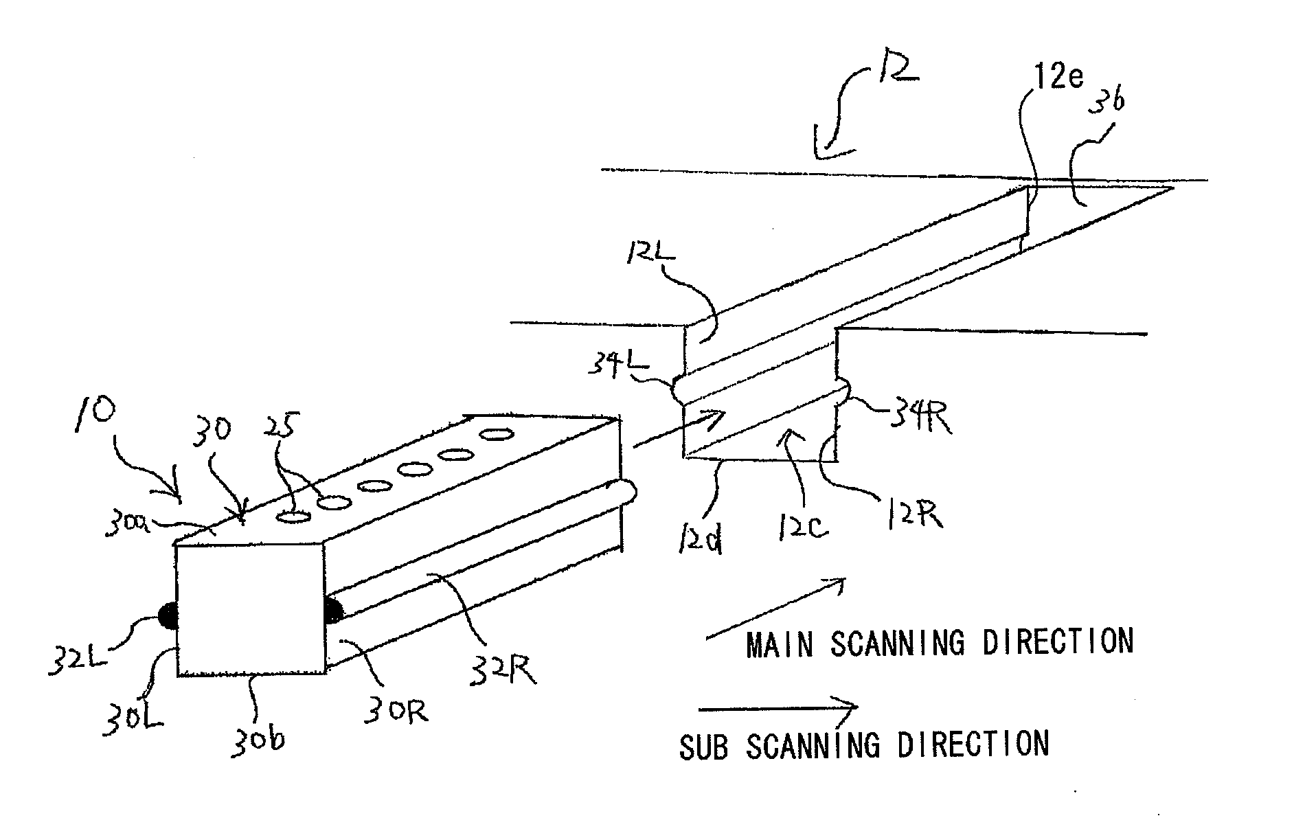
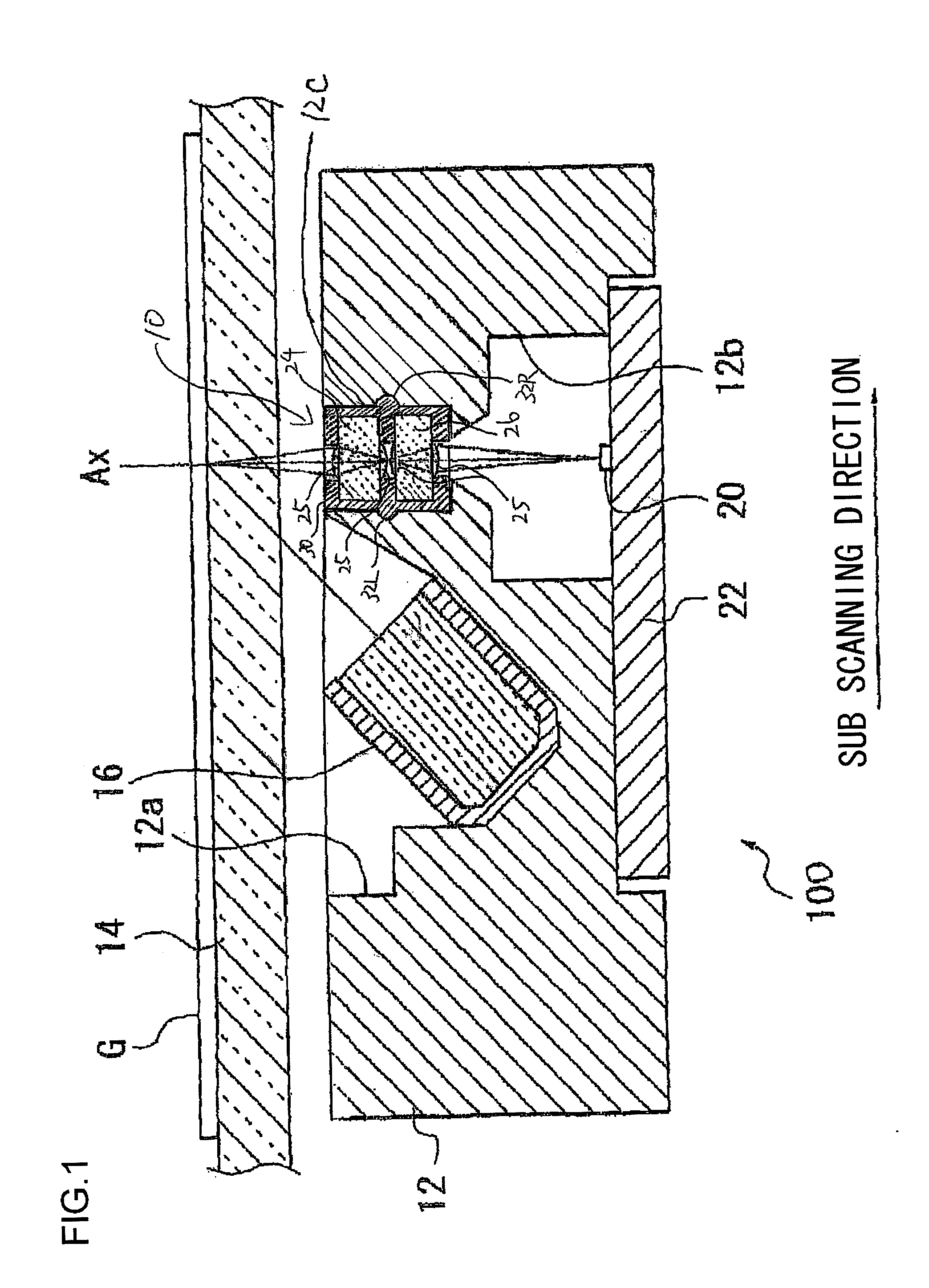
[0019]The invention will now be described by reference to the preferred embodiments. This does not intend to limit the scope of the present invention, but to exemplify the invention. FIG. 1 is a sectional view of an image reading device 100 in which the lens array unit mounting structure according to an embodiment of the present invention is used. As shown in FIG. 1, the image reading device 100 comprises a housing 12, a glass plate 14 on which a document G is placed, a line illuminator 16 for illuminating the document G with light, a lens array unit 10 for condensing light from the document G, and a line image sensor (photoelectric transducer) 20 for receiving light condensed by the lens array unit 10.

[0020]A recess 12a is formed in the upper part of the housing 12 and a recess 12b is formed in the lower part. The line illuminator 16 is diagonally fixed inside the recess 12a in the upper part. The line illuminator 16 is fixed such that the optical axis of the illuminating light pas...


PUM


Abstract

A lens array unit mounting structure mounts a lens array unit in a recess provided in a housing of an image reading device. The structure includes a right projection and a left projection provided on the lens array unit and includes a right groove and a left groove provided in the recess of the housing. The lens array unit is secured in the recess of the housing by engaging the right projection with the right groove and engaging the left projection with the left groove.

Description

BACKGROUND OF THE INVENTION[0001]1. Field of the Invention[0002]The present invention relates to a mounting structure for a lens array unit used in an image reading device.[0003]2. Description of the Related Art[0004]Some image reading devices according to the related art, such as scanners, are known to use erecting equal-magnification optical systems. The use of erecting equal-magnification optical systems allows reducing the size of devices better than reduction optical systems. In the case of image reading devices, an erecting equal-magnification optical system comprises a line light source, an erecting equal-magnification lens array, and a line image sensor.[0005]A rod lens array capable of forming an erect equal-magnification image is conventionally used as an erecting equal-magnification lens array in an erecting equal-magnification optical system. Recently, there is proposed a lens array unit formed as a stack of a plurality of transparent lens array plates built such that th...

Claims


Application Information

Patent Timeline
IPC IPC(8): G02B7/02
CPCG02B7/021H04N1/0318H04N2201/02458H04N2201/03145H04N2201/02485H04N2201/03112H04N2201/03141H04N2201/02466
Inventor SHIMMO, KATSUHIDESATO, SHIROMAMADA, HARUHIKO
Owner NIPPON SHEET GLASS CO LTD
Features
  • R&D
  • Intellectual Property
  • Life Sciences
  • Materials
  • Tech Scout
  • Unparalleled Data Quality
  • Higher Quality Content
  • 60% Fewer Hallucinations
Learn More