Sheet transporting device

a technology of transporting device and sheet, which is applied in the direction of transportation and packaging, electrographic process, instruments, etc., can solve the problems of increasing the likelihood of paper jams occurring during transportation, increasing the load of transportation, and increasing power consumption, so as to improve image reproducibility, improve the separation of sheets, and reduce the power of adsorption

Inactive Publication Date: 2010-01-28
RISO KAGAKU CORP
View PDF6 Cites 23 Cited by
  • Summary
  • Abstract
  • Description
  • Claims
  • Application Information

AI Technical Summary

Benefits of technology

[0042]However, charges are accumulated over time in the portions closing the through holes in the dielectric layer of the conveyor belt, becoming equivalent to the charges in the remaining portions of the dielectric layer of the conveyor belt. This shuts off the electrical flux lines penetrating the sheet and the upper and under sides of the sheet become uncharged, resulting in a decrease in the power of adsorbing the sheet to the dielectric layer.
[0043]Accordingly, among the through holes formed in the conveyor belt, if vertical through holes communicating with the openings formed in the dielectric layer and holes closed by the dielectric layer are formed to be distributed appropriately, sections where adsorptive power is maintained and sections where adsorptive power attenuates over time can be distributed arbitrarily in an adsorption region of the conveyor belt. Hence, in the transportation of a sheet on the conveyor belt using electrostatic adsorption, it is possible to retain the sheet in the adsorption region of the conveyor belt certainly with strong adsorptive power at the start of adsorption of the sheet and allow excess adsorptive power to attenuate over time, while keeping the adsorptive power required to transport the sheet during the transportation of the sheet. Thus, it is possible to improve image reproducibility by eliminating to some degree a disadvantage in which the directions of ink droplets jetted toward a sheet from the print heads are deflected by the influence of the charges. When the sheet is going to be ejected, coming to a position out of the last print head in the transport direction by the movement of the conveyor belt, the power of adsorbing the rear end of the sheet readily attenuates. This improves sheet separation when a sheet is ejected (drop off the conveyor belt) and improves the alignment of sheets after being ejected.
[0044]Especially, in the case where the fixed electrode includes plural divisional elements, because charges on a sheet are uncharged readily in the position of a print head between fixed electrodes, the disadvantage in which the directions of ink droplets jetted toward a sheet from the print heads are deflected ...

Problems solved by technology

When such paper is re-fed and duplex printing of the paper is performed, the forward end of the paper may warp up and collide with rollers, print heads, and like along a transport path, which increases the likelihood that a paper jam occurs during transportation.
However, according to the sheet transporting means wherein interdigital electrodes are fixed, described in Patent Document 1, because the conveyor belt 102 adheres to the comb-shaped electrodes 100, 101, the load of transportation is increased, which poses a problem of increasing power consumption.
Thus, according to this sheet transporting means, unstable adsorptive power results in unstable speed of transportation of the conveyor belt 102 and the way of movement of the conveyor belt 102 becomes intermittent, if expressed in an extreme manner, and a problem of degrading the print quality of printed images is presented.
Consequently, thickness variation occurs especially in the roller portion and the distance from the center of the roller to the surface of the convey...

Method used


Image

  • Sheet transporting device
  • Sheet transporting device
  • Sheet transporting device

Examples


first embodiment (first example , see fig.1 and fig.2)

1. First Embodiment (First Example, See FIG. 1 and FIG. 2)

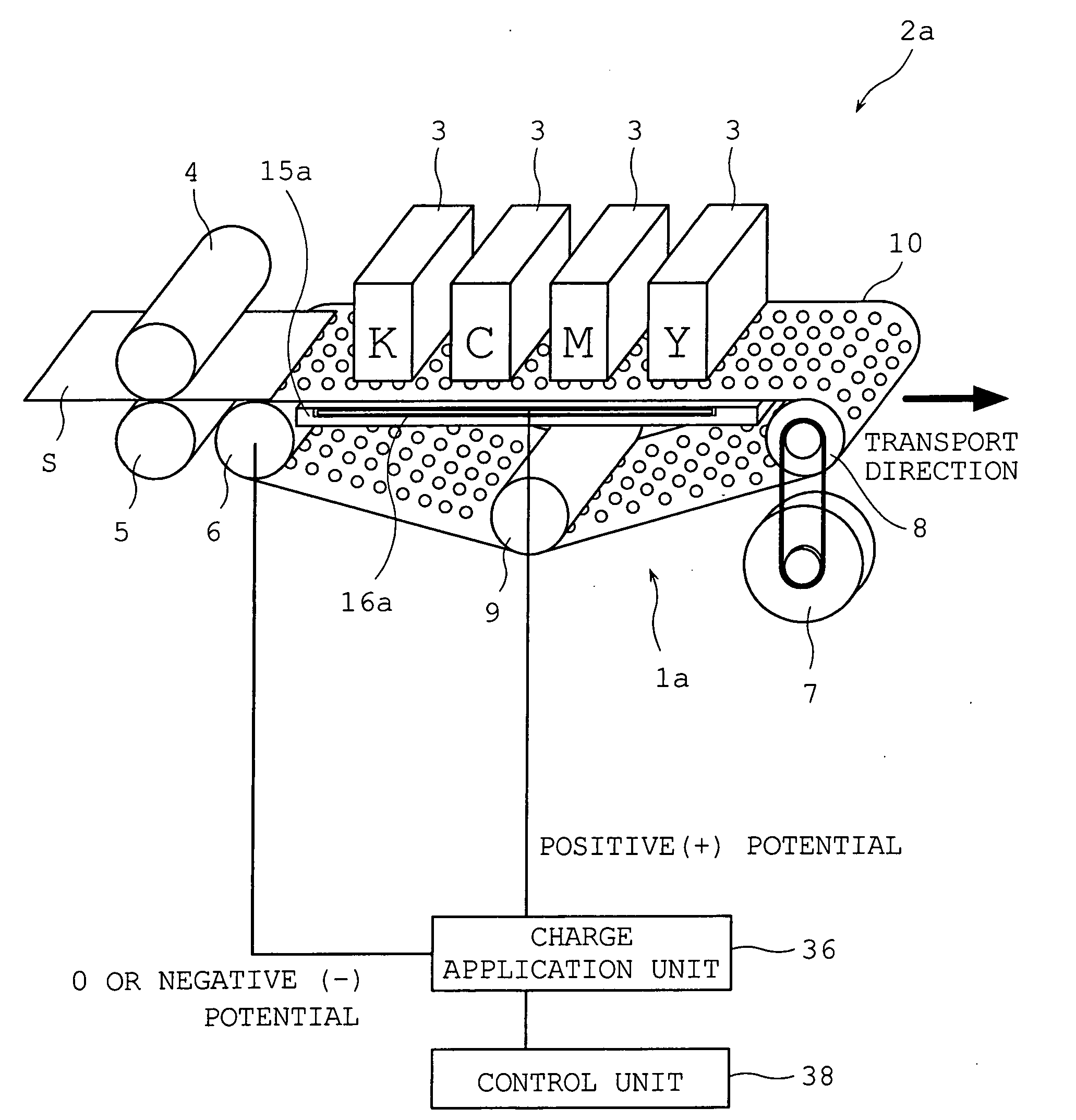
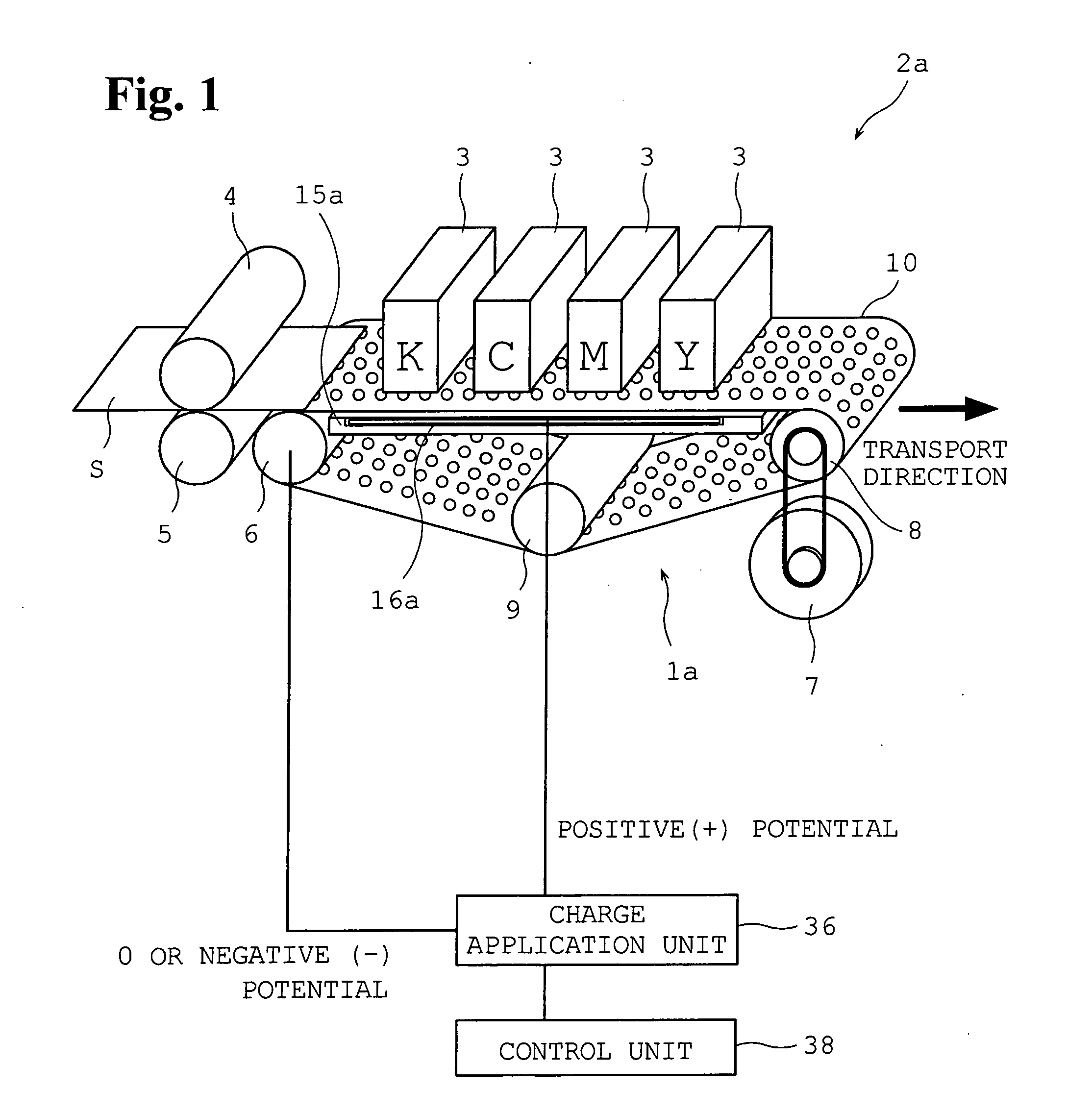
[0066]As is illustrated in FIG. 1, an image forming apparatus 2a of a first example is configured such that plural print heads 3 having different colors of inks are disposed facing down, spaced at certain intervals along a transport direction of a sheet S denoted by an arrow, and can jet ink droplets toward the sheet that is transported thereunder. In the example shown, four print heads jetting inks of four colors, C (cyan), K (black), M (magenta), and Y (yellow), respectively, are placed.

[0067]Directly under these print heads 3, a sheet transporting device 1a for transporting a sheet S along the print heads is disposed. Before the print heads 3 in the transport direction, first, a registration roller 4 and a driven roller 5 are provided adjacent to a paper feed mechanism which is not shown to feed a sheet S to the sheet transporting device 1a in the following stage.

[0068]The sheet transporting device 1a is configured such th...

second embodiment (second example , see fig.3 and fig.4)

2. Second Embodiment (Second Example, See FIG. 3 and FIG. 4)

[0083]A sheet transporting device of a second example is installed in the same image forming apparatus as the image forming apparatus 2a of the first example and the fundamental principle of electrostatic adsorption is also the same as in the first example. Therefore, the following description focuses on the structure of a conveyor belt 20 which is different from that of the first example, omitting the description of the image forming apparatus and the description of the common part of the electrostatic adsorption mechanism.

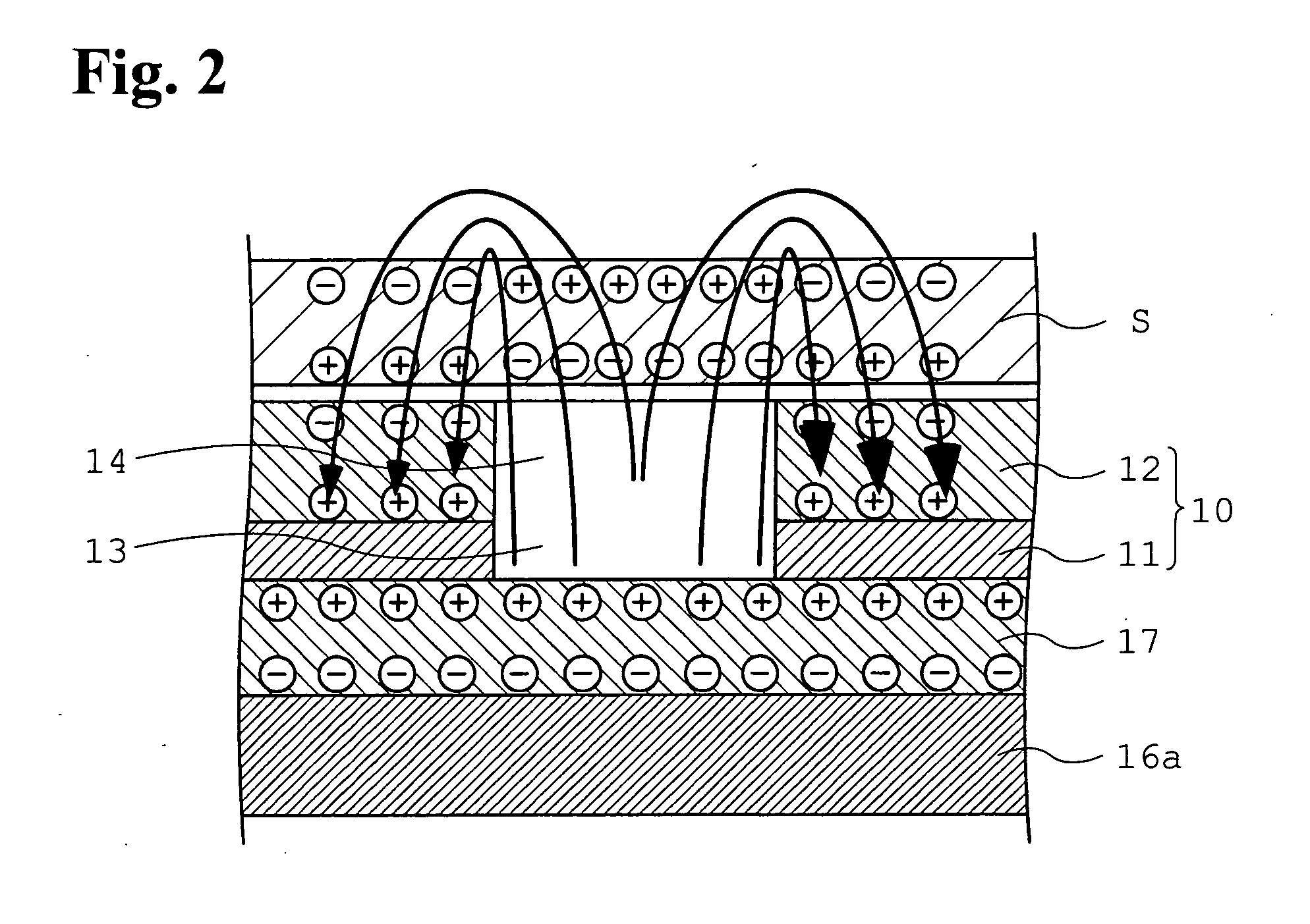
[0084]In the sheet transporting device of the first example, the through hole 13 in the conductor 11 communicates with the opening 14 in the dielectric layer 12 wherever holes are bored; that is, all holes in the conveyor belt 10 are completely pierced through holes. A dissimilar point of the second example is as follows: in some holes, there is no opening in the dielectric layer 12 formed on top of the ...

third embodiment (third example , see fig.5 and fig.6)

3. Third Embodiment (Third Example, See FIG. 5 and FIG. 6)

[0093]A sheet transporting device 1b of a third example is installed in the same image forming apparatus 2b as the image forming apparatus 2a of the first example and the fundamental principle of electrostatic adsorption is the same as in the first example. Therefore, the following description focuses on the structure of a fixed electrode 16b which is different from that of the first example, omitting the description of the image forming apparatus 2b and the description of the common part of the electrostatic adsorption mechanism.

[0094]As is illustrated in FIG. 5, underneath the above conveyor belt 10 which is the transport path of a sheet S, a platen base 15b of a rectangular plate shape which supports the conveyor belt 10 is installed. This platen base 15b includes an insulating body in which plural fixed electrodes 16b (five electrodes in the third example) are embedded spaced at a given interval. These fixed electrodes 16...


PUM


Abstract

Fixed electrodes 16a having a positive potential are disposed in positions not corresponding to the positions of print heads and covered with a dielectric layer 17. A conveyor belt 10 includes a conductor layer 11 having a negative potential and a dielectric layer 12 in the surface and has holes 13, 14 through which electrical flux lines from the fixed electrodes pass. Since electrical flux lines from the dielectric layer of the fixed electrodes pass through the holes and polarize a sheet S placed on the dielectric layer 12 of the conveyor belt 10 as well as the dielectric layer 12, the sheet is electrostatically adsorbed to the conveyor belt in the vicinity of the holes. With the movement of the conveyor belt along the fixed electrodes, the sheet is transported, while being electrostatically adsorbed to the conveyor belt. The inventive device of a simple structure provides stable adsorptive power and a stable speed of transportation and is free from ink droplet deflection by electric fields.

Description

TECHNICAL FIELD[0001]The present invention relates to a sheet transporting device that transports sheets by means of electrostatic adsorption and particularly to a sheet transporting device of an electrostatic adsorption type that can bring a lot of benefits in a sheet transporting device that is used in an image forming apparatus, forming an image on a sheet by ink jetting onto the sheet by print heads, and has a function of transporting a sheet along the print heads, while keeping the sheet in contact with a belt by electrostatic adsorption. In the present application, sheets refer to a sheet-like print medium such as, for example, printing paper, film, a rolled web of a sheet-like material, and a woven material.BACKGROUND ART[0002]In an image forming apparatus that forms an image on paper which is a sheet by aqueous ink jetting onto it from a print head, paper to which ink is transferred may be swollen and cockled. When such paper is re-fed and duplex printing of the paper is per...

Claims


Application Information

Patent Timeline
IPC IPC(8): G03G15/00
CPCB41J3/28B41J13/08B65H2404/27B65H2404/22B65H5/004
Inventor HORI, EIJI
Owner RISO KAGAKU CORP
Why Eureka
Try Eureka