
Low friction coated marked wire guide for over the wire insertion of a catheter

a marked wire guide and low friction coating technology, applied in the field of wire guides, can solve the problems of patient discomfort, general time-consuming procedure, and inability to easily advance the catheter, and achieve the effect of facilitating the catheter advance and facilitating the determination

Active Publication Date: 2010-01-28
COOK MEDICAL TECH LLC
View PDF13 Cites 4 Cited by
  • Summary
  • Abstract
  • Description
  • Claims
  • Application Information

AI Technical Summary

Benefits of technology

[0007]One embodiment of the present invention provides a wire guide that allows a user to easily advance a catheter over a wire guide and assists in the determination of where the catheter should be trimmed.
[0008]In another embodiment of the invention, a wire guide comprises a mandrel and a coating having a low coefficient of friction disposed on at least a segment of the mandrel. Each segment has a depth mark indicated by an area of coating at least partially removed from the mandrel. This marking on the wire guide allows a user to determine a trimmable length of the catheter, and the low friction coating enables the user to easily advance the catheter over the wire guide.

Problems solved by technology

If a relatively large portion of the catheter remains outside of the patient's body, the catheter may be caught on outside objects, affecting the placement of the catheter and causing the patient to experience discomfort.
This procedure is generally time consuming because it requires the physician insert the wire guide, withdraw the wire guide, cut the distal portion of the catheter and insert the catheter into the patient, although it ensures that only a small proximal portion of the catheter will be left outside of the patient's body during the interventional procedure.
However, most of the materials used for these PICC lines include silicone and urethane, which may not allow the catheter to be easily advanced over the wire guide due to friction resistance.
In addition, the utilization of these PICC line materials can lengthen the time of this procedure, causing undesired difficulty and discomfort.

Method used


Image

  • Low friction coated marked wire guide for over the wire insertion of a catheter
  • Low friction coated marked wire guide for over the wire insertion of a catheter
  • Low friction coated marked wire guide for over the wire insertion of a catheter

Examples


Embodiment Construction

[0014]The presently preferred embodiments of the invention are described with reference to the drawings. The descriptions of the preferred embodiments are exemplary and are not intended to limit the scope of the invention.

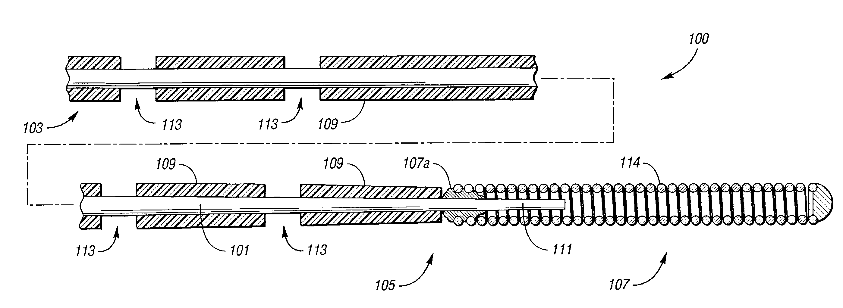
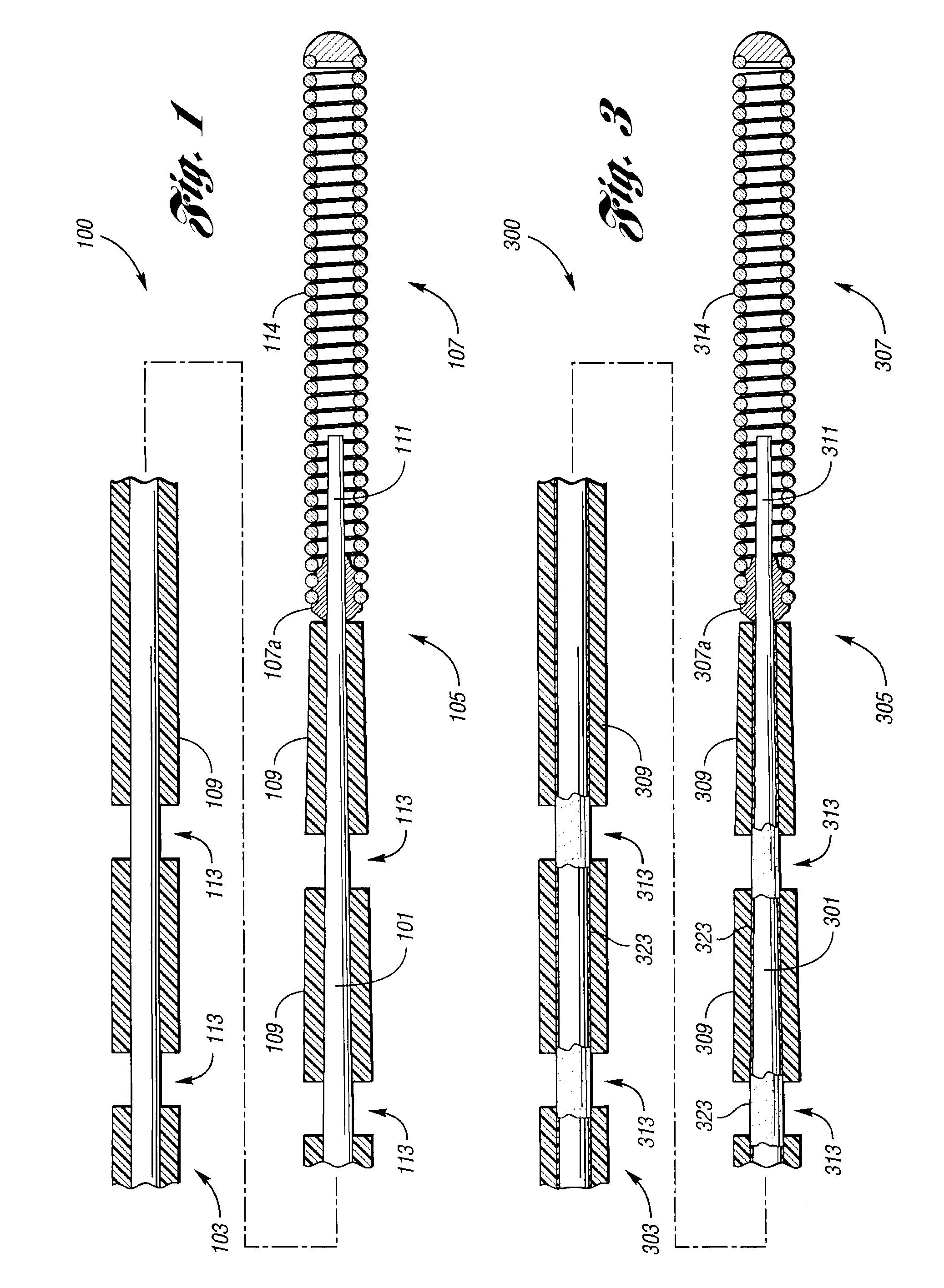
[0015]In accordance with one embodiment of the present invention, FIG. 1 illustrates a wire guide 100 generally comprising a mandrel 101, a coating 109 disposed about the mandrel 101 and wire guide depth markings 113. More specifically, the mandrel 101 has a proximal portion 103 extending to a distal portion 105. As shown, distal portion 105 includes tapered portion 111 to which a coil 107 is attached, defining a distal tip of the wire guide 100. In this embodiment, the coil 107 is attached to the distal tip 105 by a solder joint 107a. Coating 109 is disposed on at least segments of the proximal portion 103 and the distal portion 105. In this embodiment, each segment has a depth mark indicated by an area of coating at least partially removed from the mandrel 101. T...


PUM

PropertyMeasurementUnit
lengthaaaaaaaaaa
thicknessaaaaaaaaaa
diameteraaaaaaaaaa

Abstract

A wire guide includes a mandrel that has a proximal portion and a distal portion. A coating having a low coefficient of friction is disposed on at least part of the proximal portion and the distal portion of the mandrel, where a part of the proximal portion and distal portion of the mandrel without the coating indicates a marking on the wire guide. This marking on the wire guide allows a user to determine a trimmable length of a catheter, and the low friction coating enables the user to easily advance the catheter over the wire guide.

Description

CROSS-REFERENCE TO RELATED APPLICATIONS[0001]This application is a divisional of U.S. patent application Ser. No. 10 / 831,740, filed Apr. 23, 2004, entitled “LOW FRICTION COATED MARKED WIRE GUIDE FOR OVER THE WIRE INSERTION OF A CATHETER”, which claims the benefit of U.S. Provisional Patent Application Ser. No. 60 / 465,712, filed Apr. 25, 2003, each of which is hereby incorporated by reference in its entirety.BACKGROUND OF THE INVENTION[0002]The present invention relates to wire guides used for percutaneous placement of catheters and other medical devices in the vasculature of a patient.[0003]A wire guide can be used for percutaneous placement of a catheter into a vascular system. The wire guide has a proximal end that is held by a physician and a distal end that is inserted into the vascular system. In use a physician inserts an introducer needle with the wire guide into a vessel, e.g., a brachial vein, a cephalic vein. The wire guide is introduced through the introducer needle into ...

Claims


Application Information

Patent Timeline
Patent Type & Authority Applications(United States)
IPC IPC(8): B05D5/00A61L31/10A61L31/14A61M25/09
CPCA61L31/10A61L31/14C08L27/18
Inventor OSBORNE, THOMAS A.HOFFA, ANDREW K.
Owner COOK MEDICAL TECH LLC
Learn More