Igniter

a technology of ignition device and ignition switch, which is applied in the direction of burner ignition device, combustion type, lighting and heating apparatus, etc., can solve the problems of difficult release of device even for adults, danger, and difficulty for children to release safety devices, etc., and achieves the effect of quick operation, easy and safe release and convenient operation

Active Publication Date: 2010-01-28
IWATANI CORP
View PDF20 Cites 18 Cited by
  • Summary
  • Abstract
  • Description
  • Claims
  • Application Information

AI Technical Summary

Benefits of technology

[0011]Therefore, it is an object of the present invention to provide an igniter comprising a safety mechanism which is easily operated by an adult but is difficult for a child to release.

Problems solved by technology

However, although a torch burner of this kind is very easy to use when handled by an adult, since a flame can readily be produced from the nozzle, there is a risk of danger when it is used by a child.
However, in practice, a safety device of this kind may be released simply by a child, and hence there have been demands for a safety device which is difficult for child to release.
Naturally, if the structure of the safety device is made extraordinarily complex, then a safety device which is difficult for a child to release can be obtained, but this also makes the device difficult for even an adult to release, and thus impairs the usability of the torch burner.
Consequently, there has been a problem of developing a safety device which is difficult for a child to release but which still maintains good usability for an adult user.

Method used


Image

  • Igniter
  • Igniter
  • Igniter

Examples


Embodiment Construction

[0049]Below, preferred embodiments of the present invention are described in detail with reference to the accompanying drawings, and the like.

[0050]The embodiments described below are preferred concrete example of the present invention, and therefore various desirable technical restrictions are applied, but the scope of the present invention is not limited to these modes, unless a specific reference limiting the present invention is made in the following description.

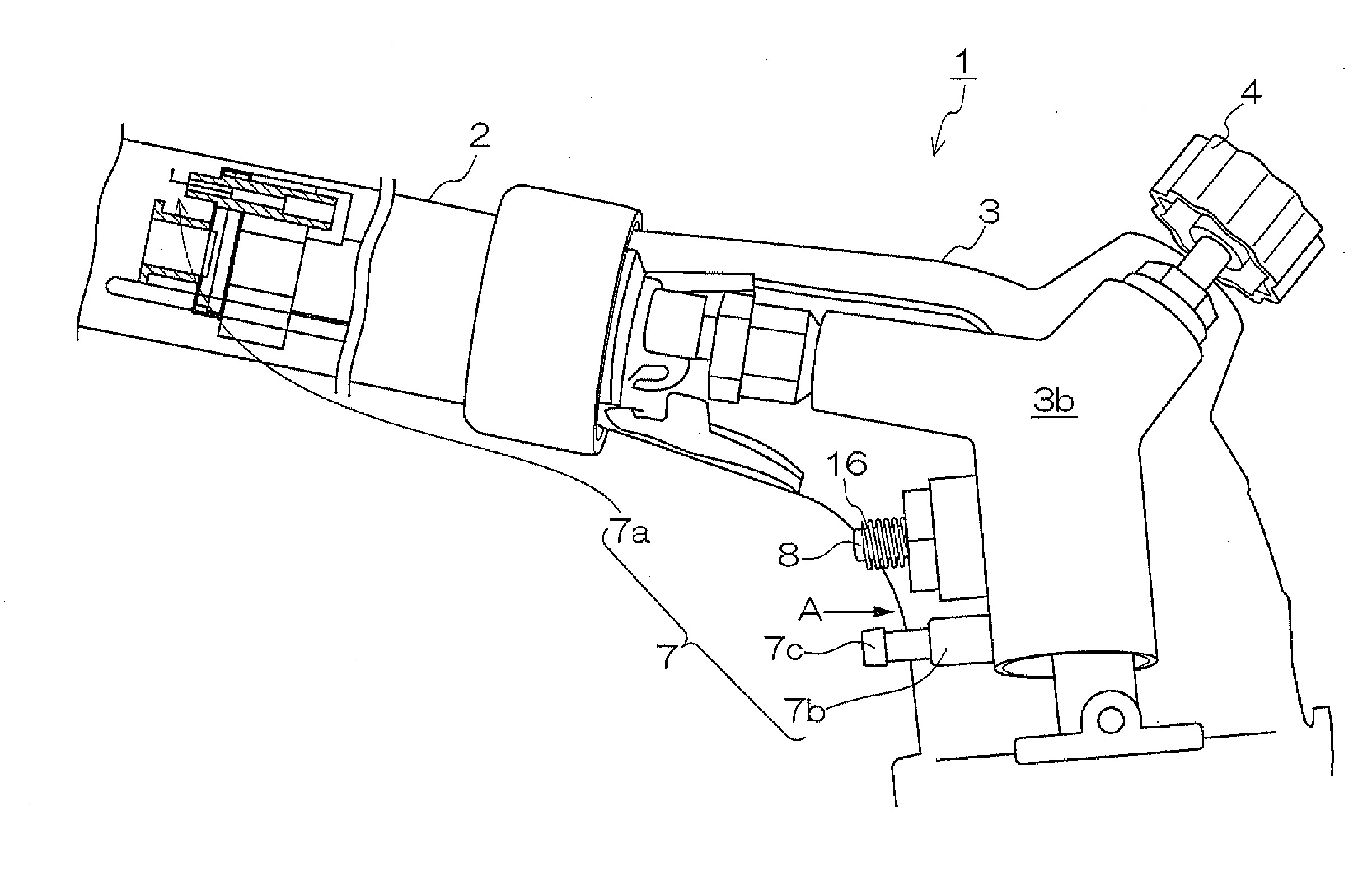
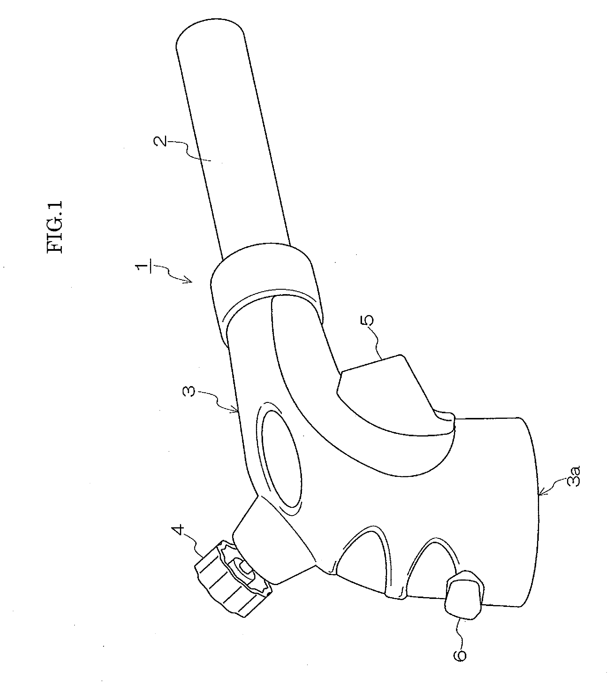
[0051]FIG. 1 is an approximate oblique diagram showing a torch burner 1, which is an example of the igniter according to the present invention. As shown in FIG. 1, the torch burner 1 comprises a metal nozzle 2 made of stainless steel, for example, which is a nozzle section that emits a flame, and a torch burner main body 3.

[0052]A cartridge installation port 3a is formed on the under side of the torch burner main body 3 and provides a fuel introduction section for installing a cartridge (not illustrated) containing a fue...


PUM


Abstract

An igniter can include a safety mechanism which is easily operated by an adult but is difficult for a child to release. In particular, an igniter can include: a nozzle section which emits a flame; a fuel introduction section; an ignition section which ignites the introduced fuel, wherein the ignition section is configured in such a manner that the fuel is ignited by movement of an ignition operating section to an ignition position; a movement restricting section having restricting sections which restrict the movement of the ignition operating section; and a permitting section which permits movement. When moving the movement restricting section, either the restricting sections or the permitting section can be disposed so as to correspond to the direction of movement of the ignition operating section.

Description

BACKGROUND OF THE INVENTION[0001]1. Field of the Invention[0002]The present invention relates to an igniter which emits a flame from a nozzle, and more particularly, to an igniter comprising a safety mechanism for guaranteeing safety.[0003]2. Description of the Related Art[0004]Conventionally, an igniter, such as a torch burner, is installed in a gas cartridge which contains gas. A torch burner of this kind is composed so that it takes the gas inside the gas cartridge into the interior of the burner, a spark discharge is then induced in the gas thus taken in, by using a piezoelectric material or the like, thereby igniting the gas, and the resulting flame is emitted from a nozzle.[0005]A composition is adopted whereby the spark discharge is generated in a straightforward fashion by means a user operating, with his or her finger, a movable plate called a trigger which is provided in the torch burner.[0006]For this reason, the user is able to take up the torch burner, in a state where ...

Claims


Application Information

Patent Timeline
Patent Type & Authority Applications(United States)
IPC IPC(8): F23Q2/16F23Q2/34
CPCF23D14/28F23D2207/00F23D14/72F23D14/38
Inventor KOTANI, HIROAKI
Owner IWATANI CORP
Why Eureka
Try Eureka