Endoscopically inserting surgical tool

a technology of surgical tools and endoscopes, which is applied in the direction of surgical forceps, surgery, medical science, etc., can solve the problems of difficult to accurately transmit a rotational force to the action mechanism at the fore distal end of the flexible cord, and achieve the effect of suppressing flexures of the flexible cord and improving the manipulability of the flexible cord in rotating an endoscopically inserted tool

Active Publication Date: 2010-01-28
FUJIFILM CORP
View PDF24 Cites 11 Cited by
  • Summary
  • Abstract
  • Description
  • Claims
  • Application Information

AI Technical Summary

Benefits of technology

[0013]Gathering from the foregoing situations, according to the present invention, the manipulability of a flexible cord in rotating an endoscopically inserted tool is improved significantly by the use of a rotary tool adjustor which is adapted to grip a proximal end portion of a flexible tube in such a way as to prohibit relative rotations therebetween and which is manipulable by way of a grip portion or portions provided on the outer peripheral side of a tubular outer shell with a far larger outside diameter as compared with the flexible tube. The grip portions of the rotary tool adjustor may be provided integrally with the outer shell or fixed on the latter by the use of a suitable fixation means. For example, the grip portion of the rotary tool adjustor can be realized by forming a number of longitudinal protuberances at intervals around the outer periphery of the outer shell or by providing a radially projecting lever or finger hook rings on the outer periphery of the outer shell.
[0014]The rotary tool adjustor may be provided fixedly on a proximal end portion of a flexible cord. However, it is more desirable for the rotary tool adjustor to be releasably fixed on a flexible cord to permit adjustments of its position in the longitudinal direction of the flexible cord. When the rotary tool adjustor is adjustable in the longitudinal direction of the flexible cord, it can be located in such a position as to optimize the axial position of the action mechanism at the distal end of the flexible cord and to suppress flexures of the flexible cord as well.

Problems solved by technology

If the rotary tool adjustor were attached on a flexible cord portion which is disposed in a free state at a position distant from the tool entrance way, it would be difficult to transmit a rotational force accurately to the action mechanism at the fore distal end of the flexible cord.

Method used


Image

  • Endoscopically inserting surgical tool
  • Endoscopically inserting surgical tool
  • Endoscopically inserting surgical tool

Examples


Embodiment Construction

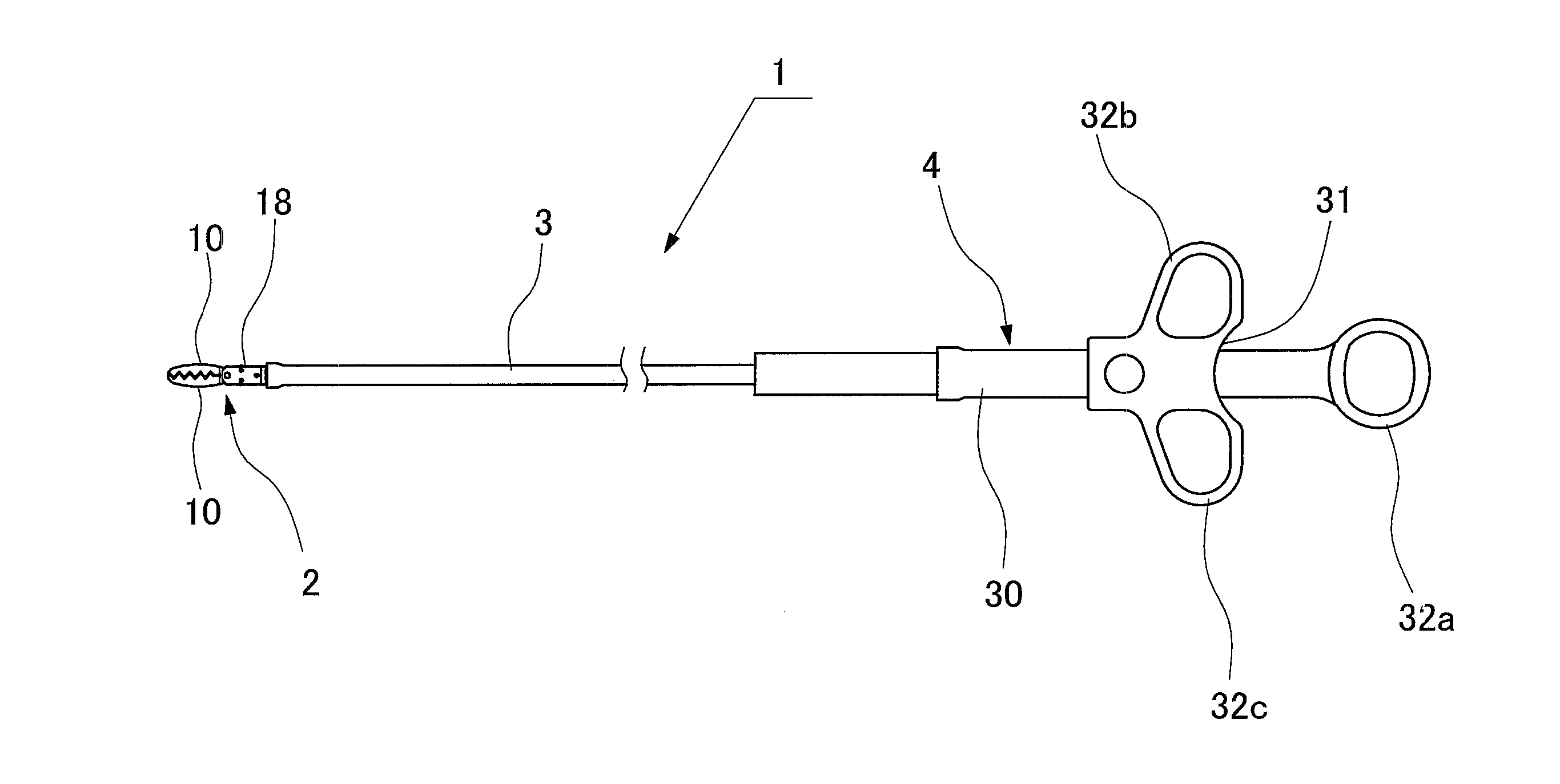
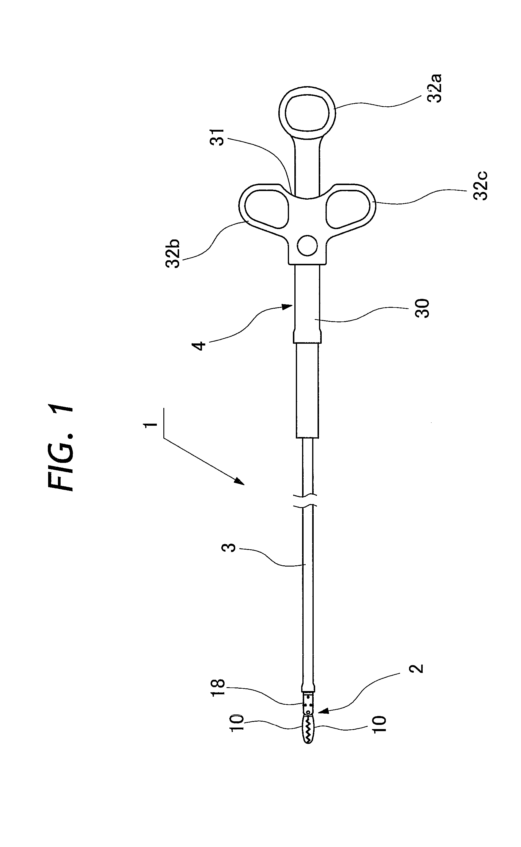
[0033]Hereafter, with reference to the accompanying drawings, the present invention is described more particularly by way of its preferred embodiments Here, the present invention is applied to forceps, taken as an example of an endoscopically inserting tool which needs to be orientated into a particular radial direction prior to performing a required action. Needless to say, the invention can be similarly applied to other endoscopically inserting surgical or bioptic tools. FIG. 1 shows general layout of a forceps 1 embodying the present invention, while FIG. 4 shows the forceps 1 which is placed in a tool guide channel of an endoscope 40.

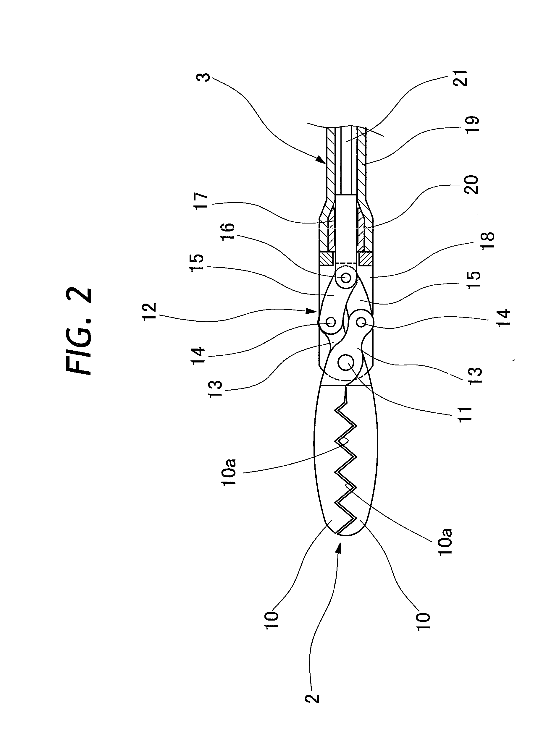
[0034]In FIG. 1, indicated at 1 is a forceps which is provided with a grasper assembly 2 at its fore distal end as an action mechanism. The grasper assembly 2 is connected to a fore distal end of a flexible cord 3 which is in turn connected to a manipulation handle 4 at its proximal end. The grasper assembly 2 and flexible cord 3 are connected with ...


PUM


Abstract

An endoscopically inserting surgical tool is composed of an elongated flexible cord to be passed through a tool guide channel on an endoscope, and a tool action mechanism mounted on a fore distal end of the flexible cord to be projected out of the tool guide channel. The flexible cord has such a length that, when the tool action mechanism is projected out of a tool exit opening at the end of the tool guide channel, a proximal end portion of the flexible cord still remains outside and rearward of a tool entrance way which is provided on a manipulating head grip of the endoscope as an approach to the tool guide channel. A proximal end portion of the flexible cord is gripped in a rotary tool adjustor which is manipulable to turn the tool action mechanism clockwise or counterclockwise together with the flexible cord in the tool guide channel of the endoscope.

Description

TECHNICAL FIELD[0001]This invention relates to an endoscopically inserting surgical or bioptic tool having an action mechanism of the tool at a distal end of an elongated flexible cord to be placed in a tool guide channel of an endoscope.TECHNICAL BACKGROUND[0002]Generally, an endoscope for medical use has an elongated flexible insertion tube extended forward from a manipulating head grip for insertion into a body cavity. On the proximal side away from the flexible insertion tube, a universal connection cable is led out from the manipulating head grip for connection to peripheral units. An endoscopic observation means including an illumination window or windows and an optical observation window is provided at a fore distal end of the endoscopic insertion tube thereby to observe and examine an intracavitary site of interest. In case a lesion is spotted as a result of an endoscopic examination, it may become necessary to give a suitable treatment to the lesion or to sample a cellular ...

Claims


Application Information

Patent Timeline
Patent Type & Authority Applications(United States)
IPC IPC(8): A61B1/00
CPCA61B17/2909A61B2017/2939A61B2017/291A61B2017/00477
Inventor AKAHOSHI, KAZUYAAKAHANE, HIDEFUMI
Owner FUJIFILM CORP
Why Eureka
Try Eureka