Wear leveling method, and storage system and controller using the same

a leveling method and flash memory technology, applied in the direction of memory adressing/allocation/relocation, instruments, computing, etc., can solve the problems of limited erase times of physical blocks, relatively low relatively high wearing of physical blocks, so as to effectively level wear of physical blocks and prolong the life of flash memory storage systems.

Active Publication Date: 2010-01-28
PHISON ELECTRONICS
View PDF10 Cites 92 Cited by
  • Summary
  • Abstract
  • Description
  • Claims
  • Application Information

AI Technical Summary

Benefits of technology

[0010]Accordingly, the present invention is directed to a wear leveling method, which may effectively le...

Problems solved by technology

However, erase times of the physical block is limited (for example, the memory blocks may be worn after ten thousand times of erase).
If a physical block is only programmed for once, and none programming is performed afterwards, wearing of the block is relatively low.
Conversely, if the physical block is repeatedly programmed and erased, wearing of the physical block is relatively high.
When a physical block is damaged due to excessive high wearing extent thereof, the damaged physical block is then put into a bad block a...

Method used


Image

  • Wear leveling method, and storage system and controller using the same
  • Wear leveling method, and storage system and controller using the same
  • Wear leveling method, and storage system and controller using the same

Examples


first exemplary embodiment

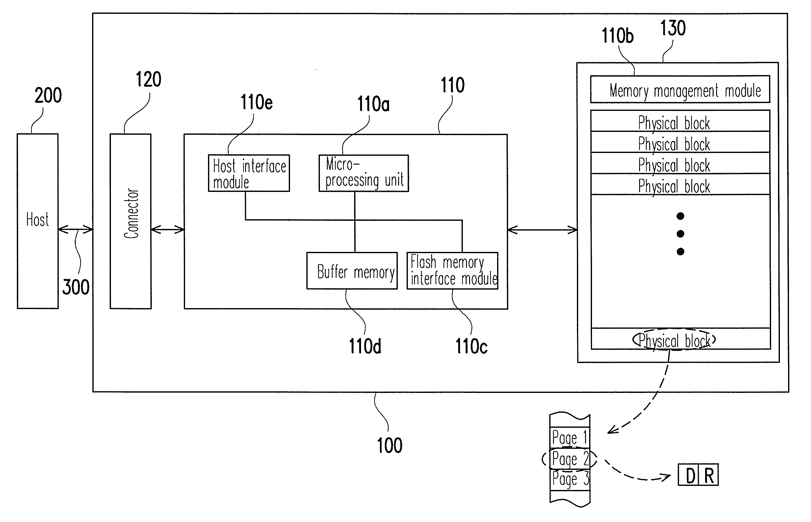
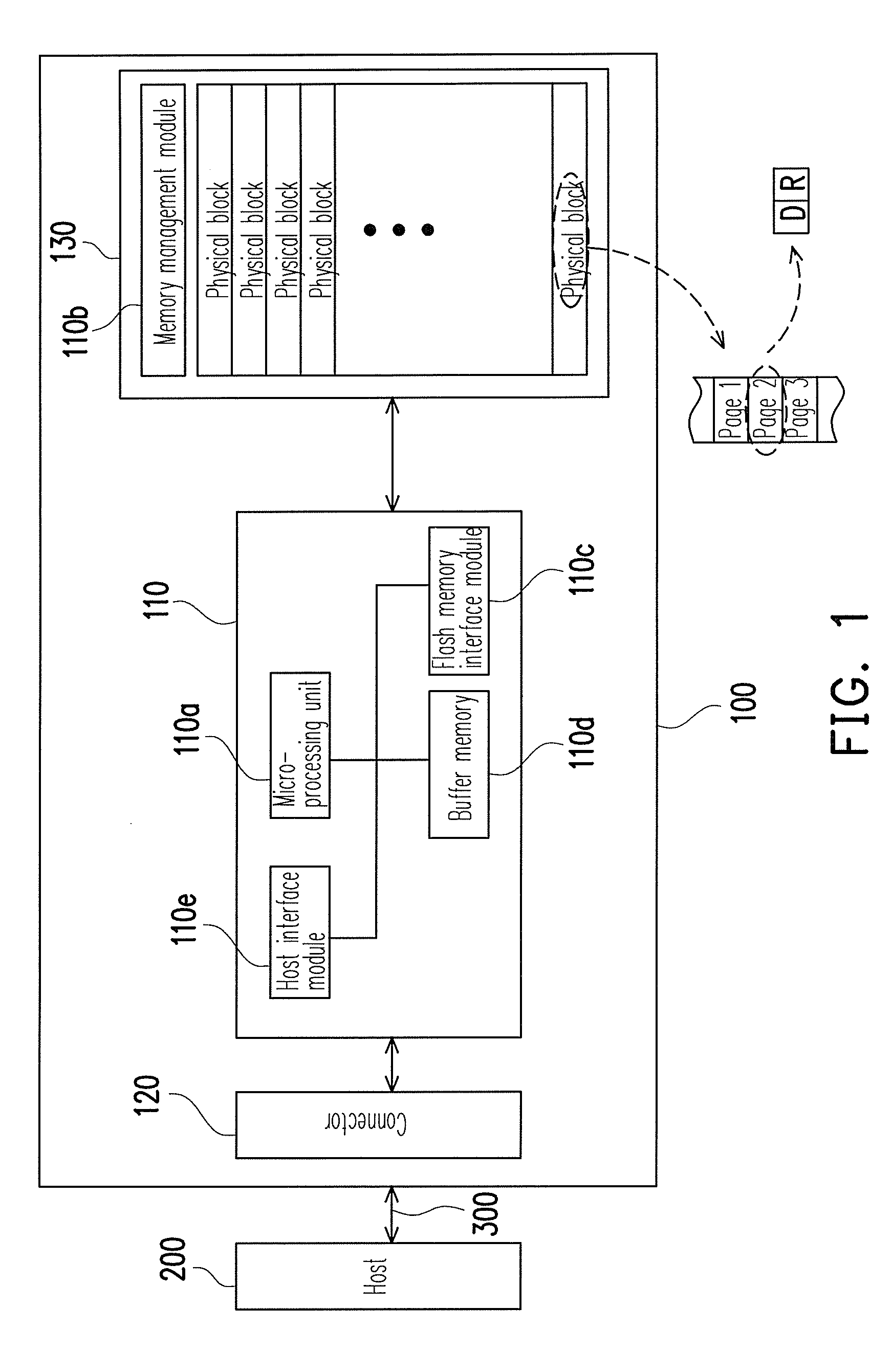
[0047]FIG. 3 is a flowchart illustrating wear leveling steps according to a first exemplary embodiment of the present invention. Wherein, the wear leveling steps are implemented by executing the machine commands of the memory management module 110b through the micro-processing unit 110a of the controller 110.

[0048]Referring to FIG. 3 when the flash memory storage system 100 is booted, in step S301, a first predetermined threshold value is set to serve as a wear-leveling start value. The wear-leveling start value represents a frequency of starting the physical blocks switching operation, wherein the greater the wear-leveling start value is, the lower the frequency of starting the physical blocks switching operation is. Conversely, the smaller the wear-leveling start value is, the higher the frequency of starting the physical blocks switching operation is. A user (for example, a storage system manufacturer) can set the first predetermined threshold value according to quality of the ut...

second exemplary embodiment

[0055]FIG. 4 is a flowchart illustrating wear leveling steps according to a second exemplary embodiment of the present invention. Wherein, the wear leveling steps are implemented by executing the machine commands of the memory management module 110b through the micro-processing unit 110a of the controller 110.

[0056]Referring to FIG. 4, when the flash memory storage system 100 is booted, in step S401, a first predetermined threshold value is set to serve as a wear-leveling start value, for example, the first predetermined threshold value is set to 500. In step S403, a random number is randomly generated to server as a memory erased count. For example, the controller 110 randomly generates the random number within a range of 0-500. In step S405, the controller stands by, and counts the memory erased count when the physical block is erased. The steps S401, S403 and S405 are the same to the steps S301, S303 and S305, and detailed descriptions thereof are not repeated.

[0057]Next, in step...


PUM


Abstract

A wear leveling method for a flash is provided, wherein the flash memory includes a plurality of physical blocks grouped into at least a data area and a spare area. The method includes setting a first predetermined threshold value as a wear-leveling start value and randomly generating a random number as a memory erased count, wherein the random number is smaller than the wear-leveling start value. The method also includes counting the memory erased count each time when the physical blocks are erased and determining whether the memory erased count is smaller than the wear-leveling start value, wherein a physical blocks switching is performed between the data area and the spare area when the memory erased count is not smaller then the wear-leveling start value. Accordingly, it is possible to uniformly use the physical blocks, so as to effectively prolong a lifetime of the store system.

Description

CROSS-REFERENCE TO RELATED APPLICATION[0001]This application claims the priority benefit of Taiwan application serial no. 97127941, filed on Jul. 23, 2008. The entirety of the above-mentioned patent application is hereby incorporated by reference herein and made a part of this specification.BACKGROUND[0002]1. Technology Field[0003]The present invention relates to a wear leveling method. More particularly, the present invention relates to a wear leveling method for a flash memory, a storage system and a controller using the same.[0004]2. Description of Related Art[0005]With a quick developing of digital camera, cell phone camera and MP3, demand of storage media by customers is increased greatly. Since a flash memory has the advantages of non-volatile, energy saving, small size and none mechanical structure etc., it is suitable for portable applications, and especially for portable battery-powered products. A memory card is a storage device applying an NAND flash memory as the storage...

Claims


Application Information

Patent Timeline
IPC IPC(8): G06F12/02
CPCG06F2212/7211G06F12/0246
Inventor CHEN, RUEI-CIANYEH, CHIH-KANGSENG, KIAN-FUI
Owner PHISON ELECTRONICS
Why Eureka
Try Eureka