
Pump

a technology of pumping system and pumping chamber, which is applied in the direction of piston pump, separation process, instrument, etc., can solve the problems of gaseous gaseous gaseous solution, difficult to precisely pump the solution routinely used in chromatography, and residues

Active Publication Date: 2010-02-04
WATERS TECH CORP
View PDF38 Cites 28 Cited by
  • Summary
  • Abstract
  • Description
  • Claims
  • Application Information

AI Technical Summary

Benefits of technology

The present invention is about devices and methods for propelling fluids. One embodiment of the invention is a device that includes a primary pump, an accumulator pump, a drive means, a valve means, and a control means. The primary pump has a primary piston and a primary chamber. The accumulator pump has an accumulator piston and an accumulator chamber. The valve means is in fluid communication with the primary pump and the accumulator pump. The control means issues signal commands to the valve means to move between a first position and a second position. The device can propel fluids from the primary pump to the accumulator pump in a serially pumped pump in which fluid flows from the primary pump to the accumulator pump. The device can also check for system failure by powering the primary pump in the intermediate position and comparing the pressure values to control values or a rate of decay. The technical effects of the invention include improved fluid propulsion, reduced pressure perturbations, and improved system failure detection.

Problems solved by technology

Some of the solutions routinely used in performing chromatography are difficult to pump precisely due to the change of volume of the liquid as it is compressed and undergoes changes in temperature.
Some of the solutions are corrosive, leave residue, dissolve mechanical parts of the pump, or become gaseous when subjected to changes in pressure.
However, if the composition of the solution is changing over time, the difficult task of maintaining constant flow to a column, cartridge or capillary becomes even more complex.

Method used


Image

  • Pump
  • Pump
  • Pump

Examples


Embodiment Construction

[0046]The present invention wilt be described in detail as a pump for use in chromatography with the understanding that the invention has utility and application wherever propelling fluids is desired. The pump will be described as a serial pump for capillary chromatography. However, the present discussion is directed to preferred embodiments and should not be perceived as limiting.

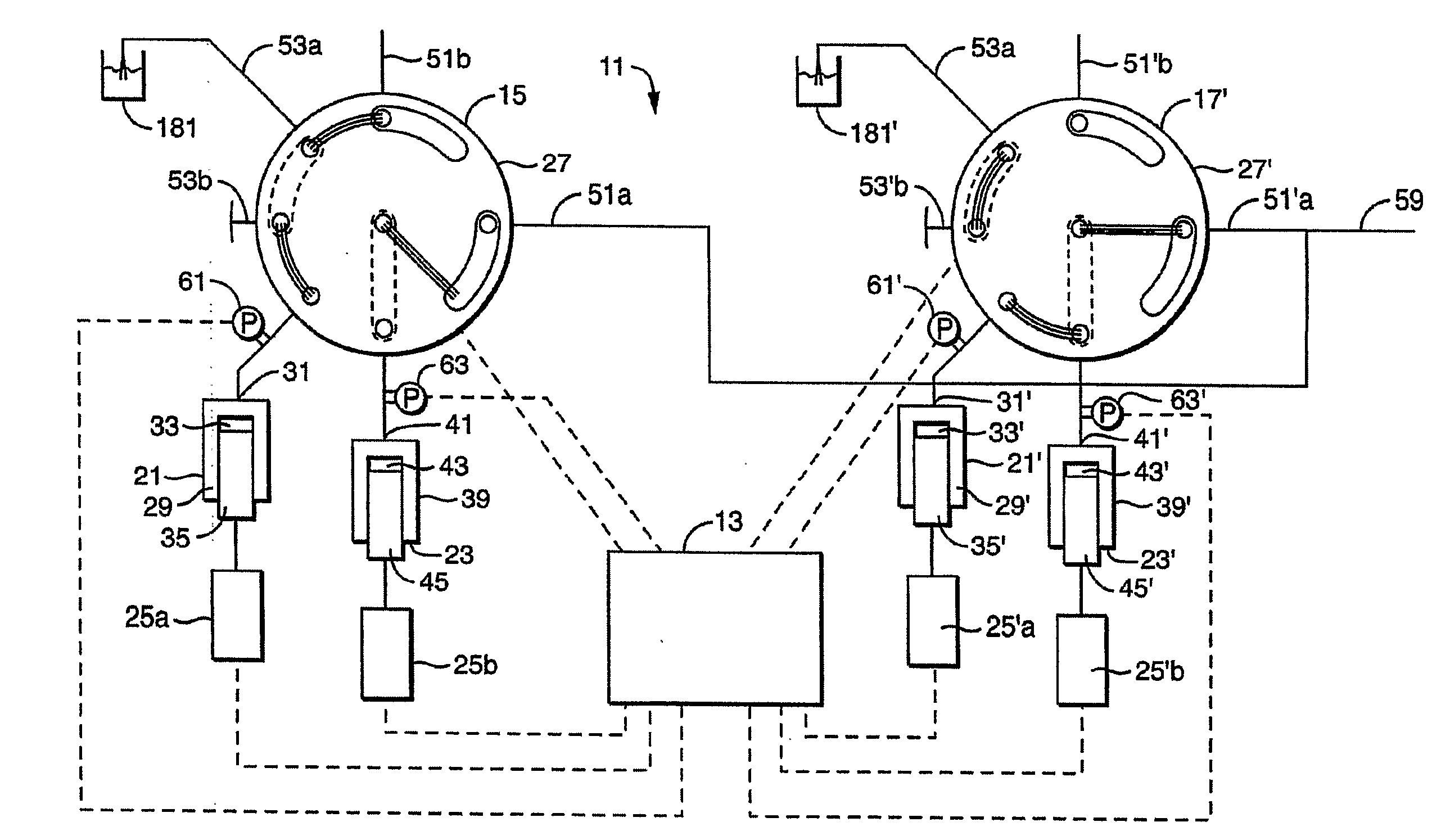
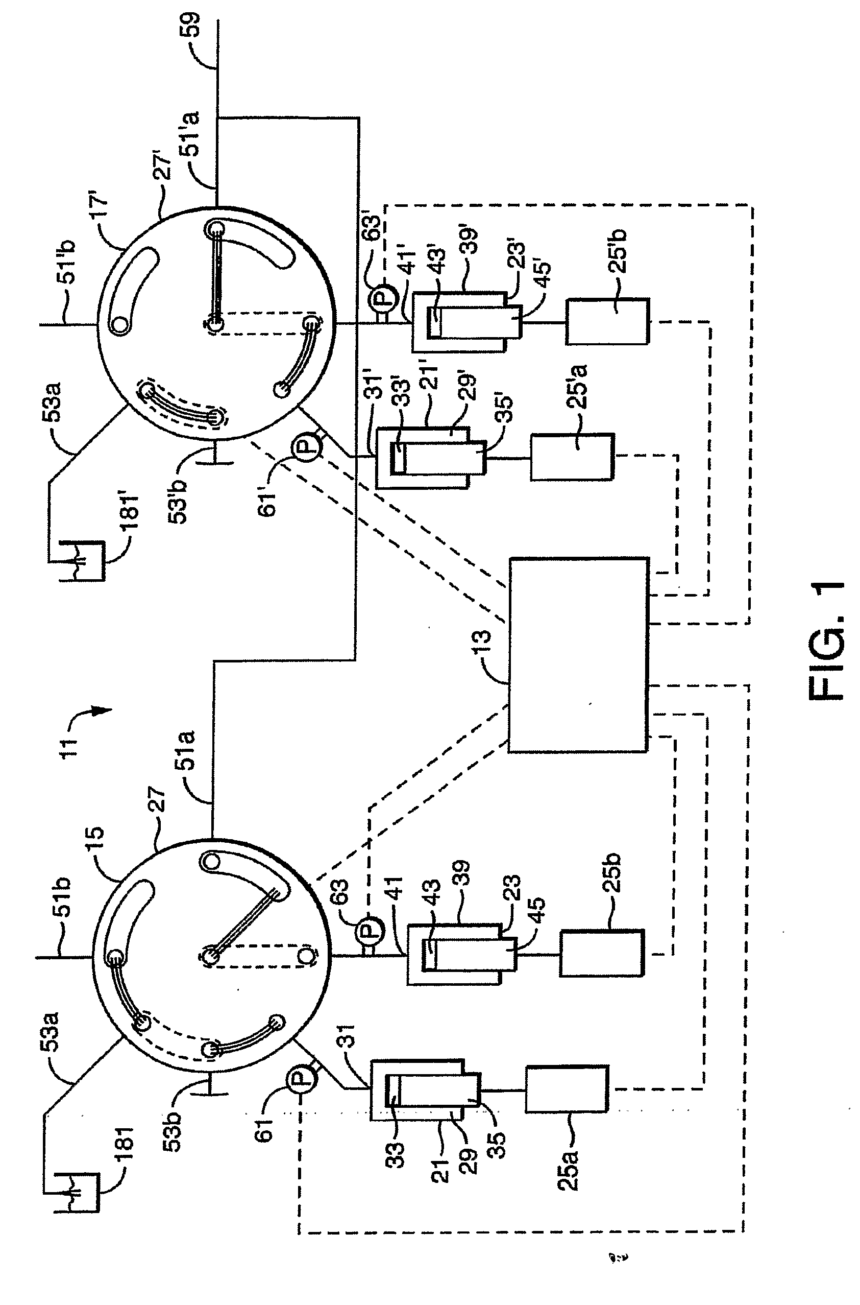
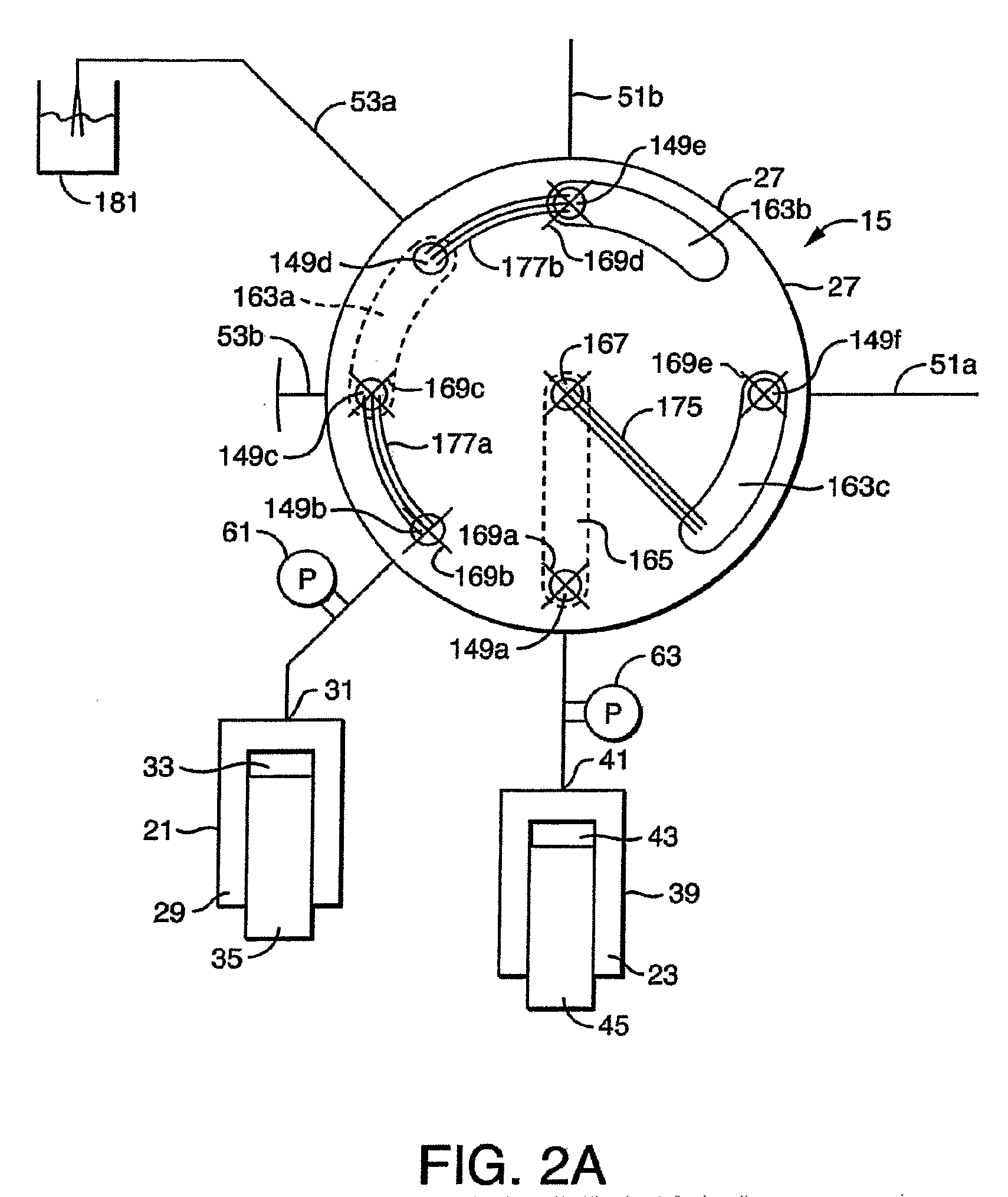
[0047]Turning now to FIG. 1, one embodiment of the present invention, directed to a device for propelling fluid, a serial capillary scale pump, generally designated by the numeral 11, is depicted. The pump 11 has control means 13 and two pump assemblies, a first pump assembly 15 and a second pump assembly 17. First pump assembly 15 is substantially identical to second pump assembly 17. For purposes of clarity, this discussion will describe pump assembly 15 in detail with the understanding that the discussion, unless otherwise noted will apply equally to second pump assembly 17. And, although two pump assem...


PUM


Abstract

Embodiments of the present invention are directed to devices and methods for propelling fluids that feature at least one first pump assembly having a primary pump, an accumulator pump, drive means, valve means and control means. The valve means moves between the first position and the second position as the accumulator pump and primary pump alternate between a loading movement and a pump movement. The control means is in signal communication with the accumulator pump, the primary pump and the valve means. The control means issues signal command to the accumulator pump to assume the loading movement and the pump movement and the primary pump to assume the loading movement and pump movement in coordination with the movement of the valve means such that fluids are propelled from the first outlet.

Description

CROSS REFERENCE TO RELATED APPLICATIONS[0001]This application claims benefit of U.S. Provisional Application No. 60 / 730,719, filed Oct. 27, 2005, (Attorney Docket No. 19921 / 59) the content of which is incorporated herein by reference.STATEMENT REGARDING FEDERAL SPONSORSHIP[0002]The present invention was not made or developed with Federal sponsorship.FIELD OF INVENTION[0003]This invention relates to pumps and pumping systems. Embodiments of the present invention have particular utility in pumps used for chromatography.BACKGROUND OF THE INVENTION[0004]Embodiments of the present invention are directed to pumps, pumping systems, valves used to operate such pumps and pumping systems and methods of using such pumps and pumping systems. The pumps and pumping systems of the present invention have particular utility in applications in which a constant flow is desired.[0005]Chromatography is the separation of mixtures of compounds in solution as the solution passes through or over an immobile...

Claims


Application Information

Patent Timeline
Patent Type & Authority Applications(United States)
IPC IPC(8): E03B5/00
CPCB01D15/14B01D15/163F04B7/0007F04B13/00F04B23/06G01N2030/326G01N30/32Y10T137/86147Y10T137/86823
Inventor MOELLER, MARK W.MCCORMICK, DANIEL J.LUONGO, JOSEPH A.
Owner WATERS TECH CORP
Learn More