Heat sink assembly

Inactive Publication Date: 2010-02-04
FU ZHUN PRECISION IND SHENZHEN +1
View PDF8 Cites 5 Cited by
  • Summary
  • Abstract
  • Description
  • Claims
  • Application Information

AI Technical Summary

Benefits of technology

[0006]A heat sink assembly includes a base, a fin group located at a top of the base, a heat pipe connecting the base and the fin group together, a fan mounted on a side of the fin group and a supporting bracket mounted on the base and supporting

Problems solved by technology

Thus, the heat pipes are prone to becoming deformed when subjected to shock or vibration during drop test, transportation or use.

Method used


Image

  • Heat sink assembly
  • Heat sink assembly
  • Heat sink assembly

Examples


Embodiment Construction

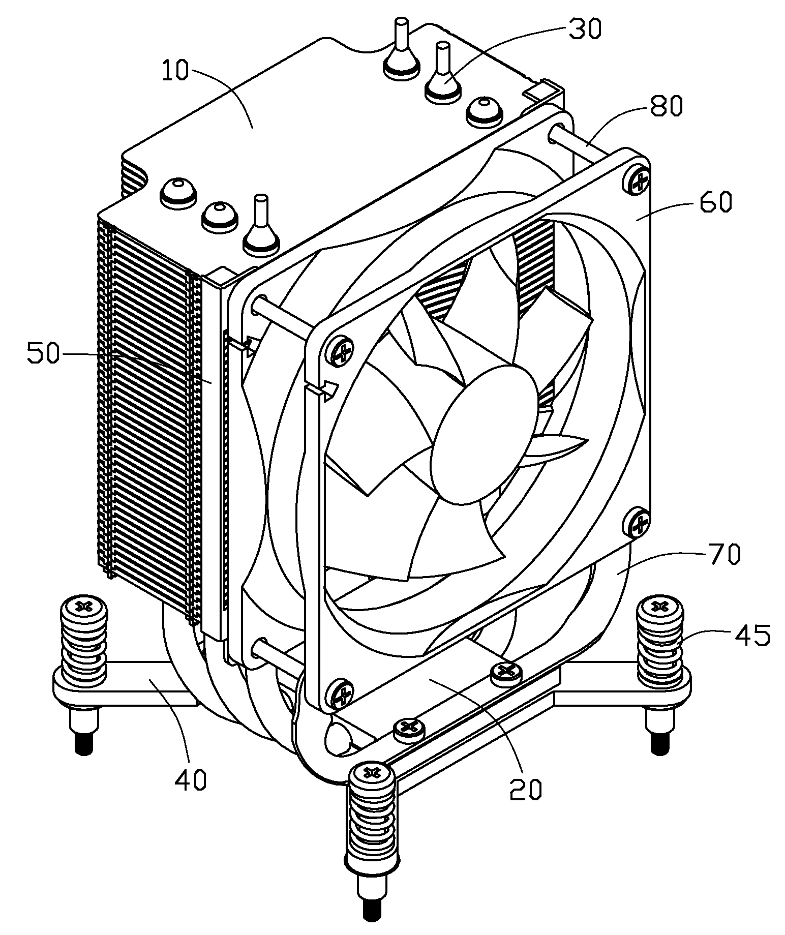
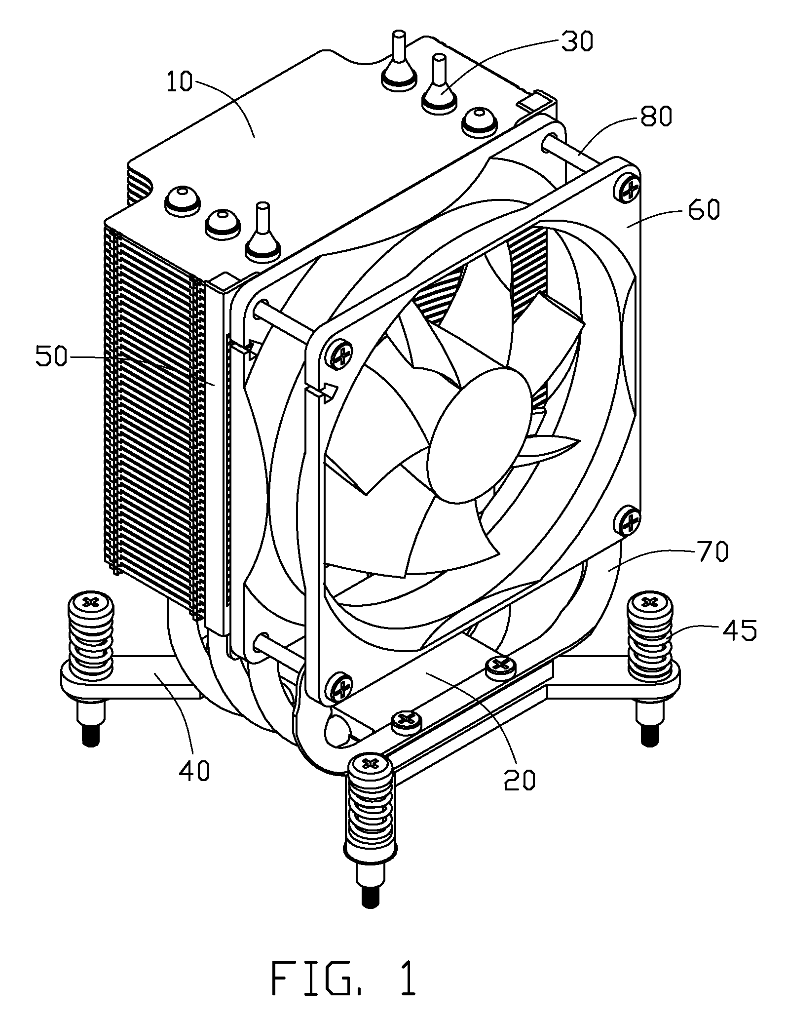
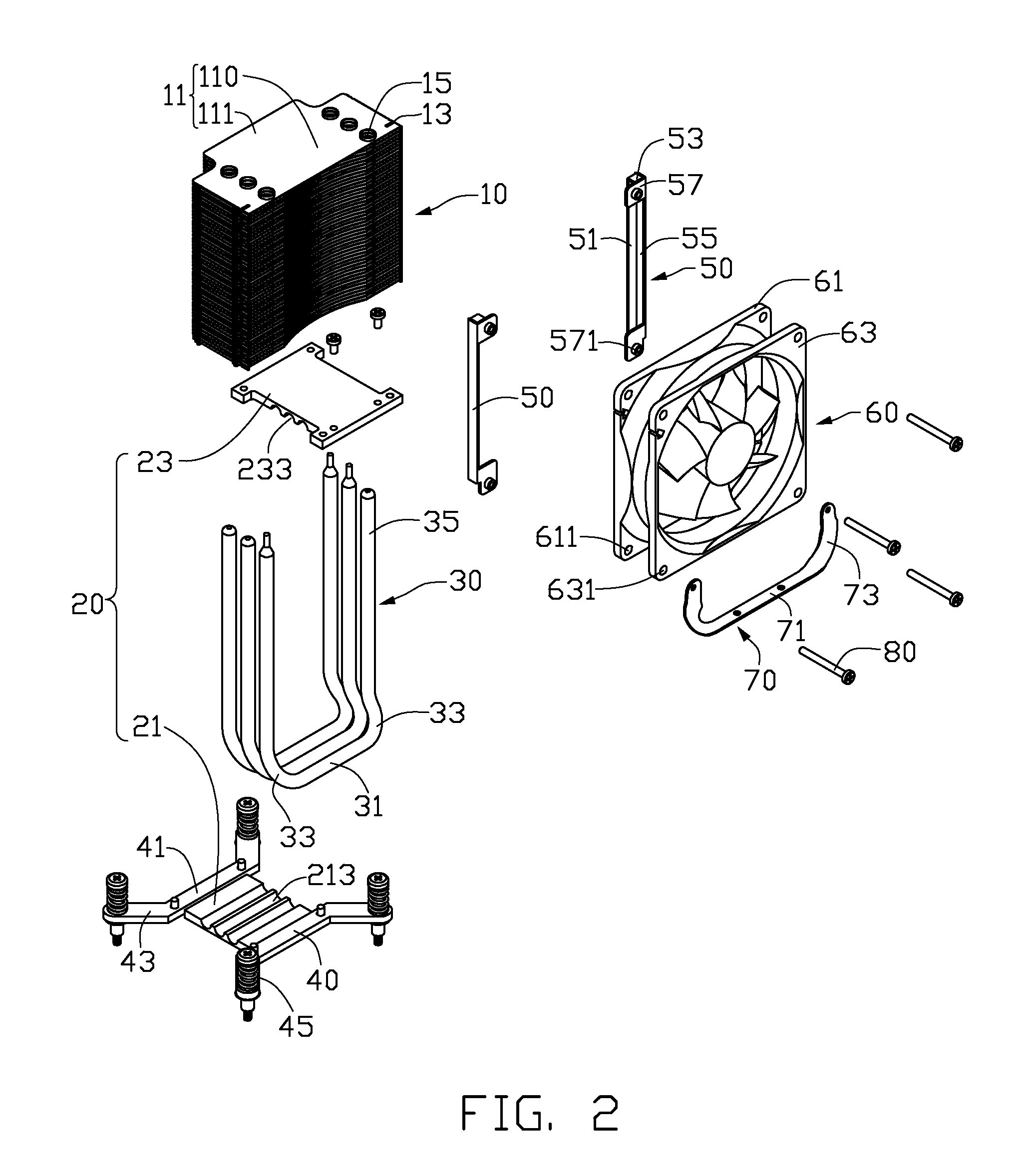
[0012]Referring to FIGS. 1-2, a heat sink assembly is used to dissipate heat generated by an electronic component (not shown) mounted on a printed circuit board. The heat sink assembly comprises a base 20 contacting with the electronic component, a fin group 10 located at a top of the base 20, three U-shaped heat pipes 30 connecting with the base 20 and the fin group 10, a fan 60 mounted on a front side of the fin group 10, and a supporting bracket 70 mounted on the base 20 and abutting against and connecting with the fan 60.

[0013]The fin group 10 comprises a plurality of parallel T-shaped fins 11. Each fin 11 comprises a rectangular body 110 and a rectangular extending portion 111 extending from a centre of a rear edge of the body 110. The extending portion 111 is smaller than the body 110. Each fin 11 forms a pair of clasps (not labeled) at lateral edges of the body 10 to clasp an adjacent fin 11 therebelow. Each fin 11 defines three pair of through holes 15 at lateral ends of the...


PUM


Abstract

A heat sink assembly includes a base, a fin group located at a top of the base, a heat pipe connecting the base with the fin group, a fan mounted on a side of the fin group and a supporting bracket mounted on the base and supporting the fan. The supporting bracket includes a mounting portion secured on the base and a pair of supporting arms extending from the mounting portion and fixed to the fan. Four screws extend through the fan to threadedly engage with the fin group. Lower two of the screws also extend through the supporting arms of the supporting bracket whereby the supporting bracket also connects with the fan.

Description

BACKGROUND OF THE INVENTION[0001]1. Field of the Invention[0002]The present invention relates to a heat sink assembly, and more particularly to a heat sink assembly having a supporting bracket to reinforce the whole strength of the heat sink assembly.[0003]2. Description of Related Art[0004]Nowadays, numerous heat sinks are used to dissipate heat generated by electronic devices. A tower type heat sink is a common structure of the heat sinks. The tower type heat sink generally comprises a base, a plurality of fins parallel to the base and a plurality of heat pipes mechanically and thermally connecting the base and the fins together. A fan is mounted on a side of the fins. The heat sink and the fan are supported only by the heat pipes. Thus, the heat pipes are prone to becoming deformed when subjected to shock or vibration during drop test, transportation or use.[0005]Thus, it is desired to devise a heat sink assembly which has a strengthened structure to improve shock resistance ther...

Claims


Application Information

Patent Timeline
IPC IPC(8): F28F7/00
CPCF28D15/0266F28F1/32H01L23/3672H01L23/4006H01L23/427H01L2924/0002H01L23/467F28D15/0275H01L2924/00
Inventor WU, YI-QIANGCHEN, CHUN-CHI
Owner FU ZHUN PRECISION IND SHENZHEN
Why Eureka
Try Eureka