
Differential transmission signal cable and composite cable containing the same

a transmission signal and cable technology, applied in the direction of cables, insulated conductors, conductors, etc., can solve the problems of signal wire damage, short circuit of conductors, signal wire damage, etc., and achieve the effect of high reliability

Active Publication Date: 2010-02-04
SUMITOMO ELECTRIC IND LTD +1
View PDF6 Cites 38 Cited by
  • Summary
  • Abstract
  • Description
  • Claims
  • Application Information

AI Technical Summary

Benefits of technology

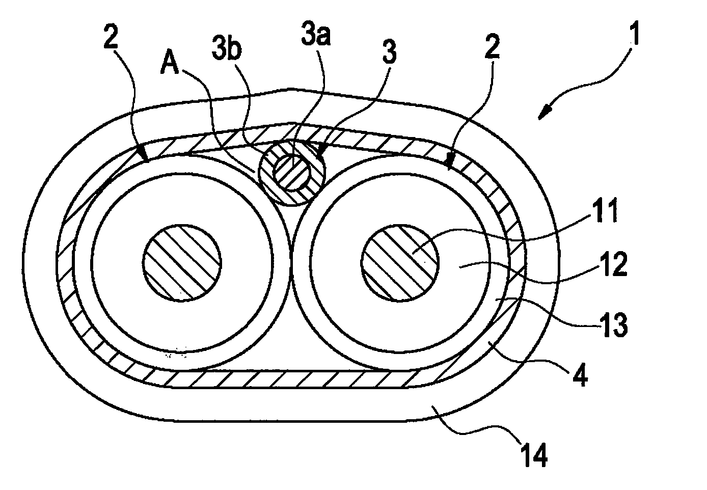
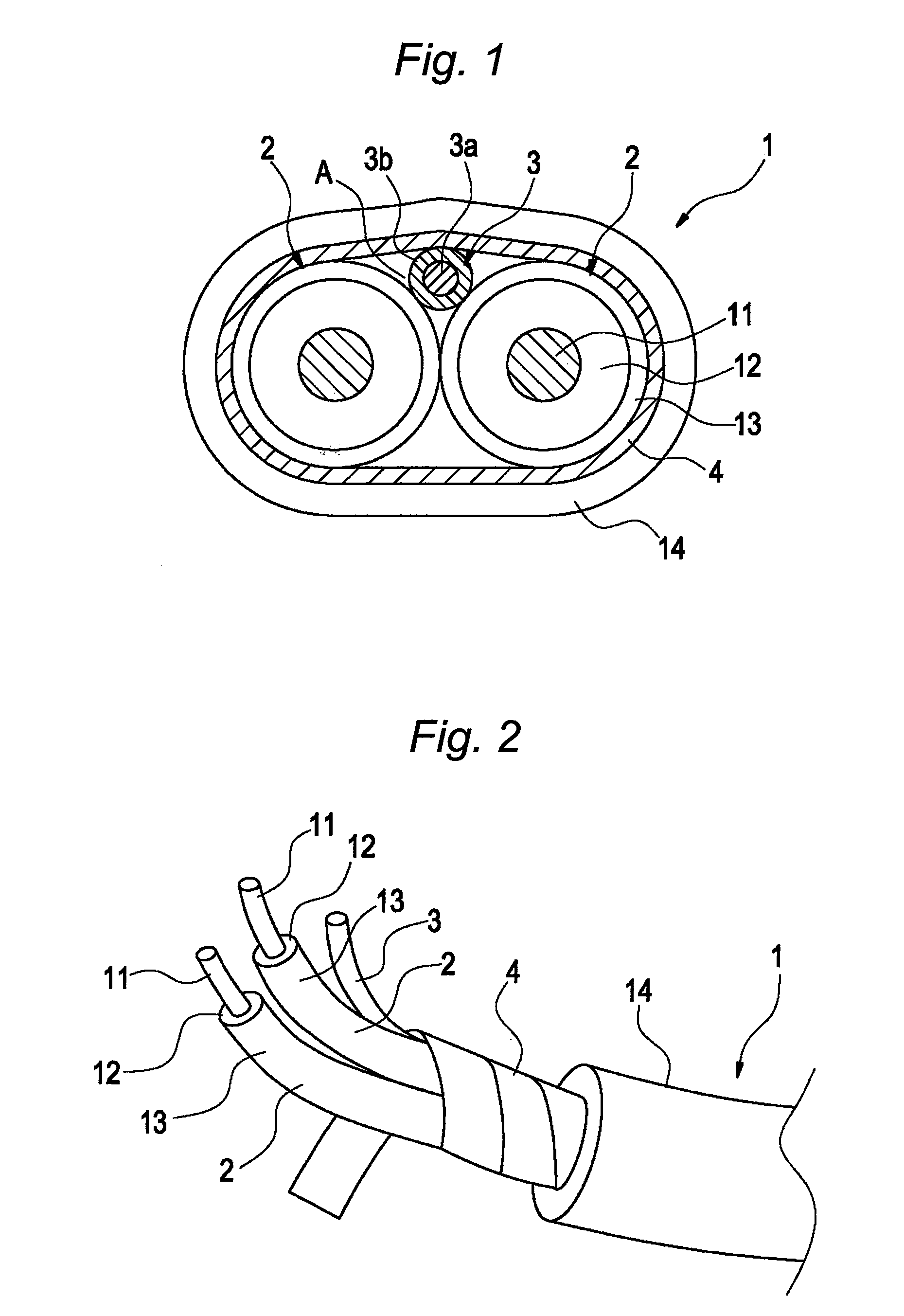
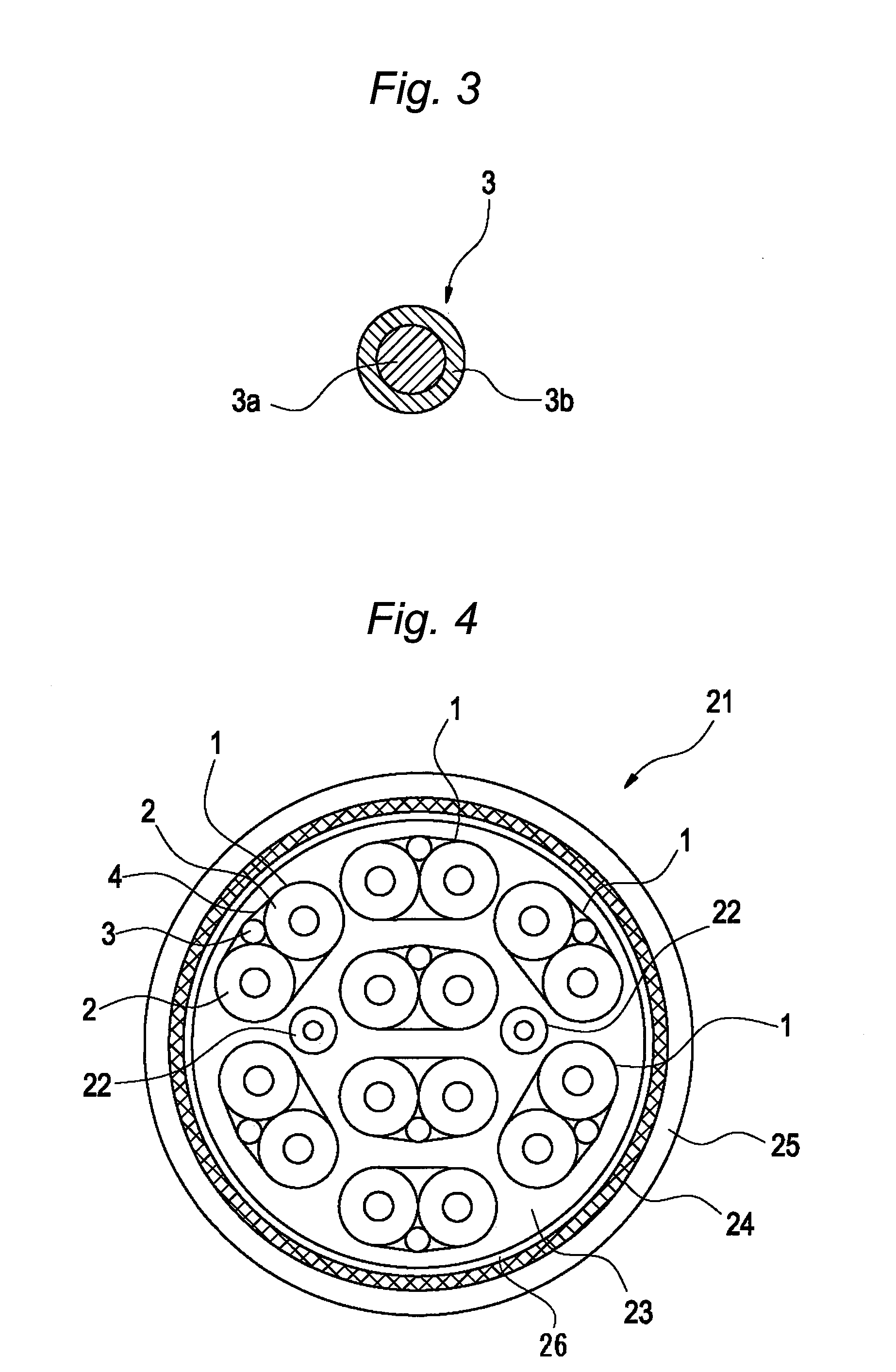
The present invention provides a differential transmission signal cable that is reliable and prevents damage to the signal wire caused by the drain wire. Additionally, the invention provides a composite cable that includes this differential transmission signal cable.

Problems solved by technology

The technical problem addressed in this patent text is to prevent damage to the signal wire caused by the depressed drain wire in differential transmission signal cables equipped with a drain wire.

Method used


Image

  • Differential transmission signal cable and composite cable containing the same
  • Differential transmission signal cable and composite cable containing the same
  • Differential transmission signal cable and composite cable containing the same

Examples


example

[0034]A test for checking whether or not an adverse influence was given was carried out under such a condition that a drain wire without a covering film and another drain wire having the covering film were depressed against a single wire, respectively. Under such a condition that a buzzer was connected to one terminal of the signal wire and one terminal of the drain wire, the drain wire was positioned over the signal wire in such a manner that the drain wire was intersected perpendicular to the signal wire, and the drain wire was depressed against the signal wire, and thereafter, such a depression force was measured when the buzzer sounded because the drain wire broke through both a skin layer and a dielectric layer of the signal wire and, thereby become shortcircuited with a central conductor.

[0035]As to a central conductor which constitutes a signal wire, a stranded wire was employed by stranding 7 pieces of tin-plated annealed copper wires, whose diameter was 0.30 mm (namely, AWG...


PUM


Abstract

A differential transmission signal cable is provided. The differential transmission signal cable includes one pair of signal wires including a central conductor covered by an insulating layer, a drain wire arrayed along the signal wires, and an outer conductor for covering the signal wires and the drain wire. The drain wire is covered by a covering film made of a semi-conductive material having flexibility and containing an electrically conductive filler.

Description


Claims


Application Information

Patent Timeline
Owner SUMITOMO ELECTRIC IND LTD
Learn More