Apparatus

a technology of subs and accessories, applied in mechanical equipment, yielding couplings, couplings, etc., can solve the problems of vibration transmission, wear of guides and pistons, and prone to wear of guides, so as to reduce the formation of adverse steps

Inactive Publication Date: 2010-02-04
TPT PRECISION ENG
View PDF8 Cites 5 Cited by
  • Summary
  • Abstract
  • Description
  • Claims
  • Application Information

AI Technical Summary

Benefits of technology

[0013]The one or more guides preferably each include a shoulder adjacent each of and between the first and the second limit of movement to minimise adverse step formation as the one or more guides wear.

Problems solved by technology

The applicant has discovered that the guides and the mounting of the guides are areas prone to wear.
In particular the applicant has discovered that the piston tends to wear the guides along a region corresponding to the usual range of movement of the piston.
This results in the formation of a raised step adjacent the limits of movement of the piston.
This step is adverse to performance in that whenever the piston moves beyond its usual range of movement, e.g. when the cushion sub is experiencing greater than the usual vibration, the piston strikes the step causing vibration to be transmitted.
This of course places limits on the service life of the cushion sub.
Testing has shown that the mounting of the guides within the head is another area where wearing is a problem.
Testing of various hardened materials to mount the guides has been found to yield unsatisfactory results.

Method used


Image

  • Apparatus
  • Apparatus
  • Apparatus

Examples


Embodiment Construction

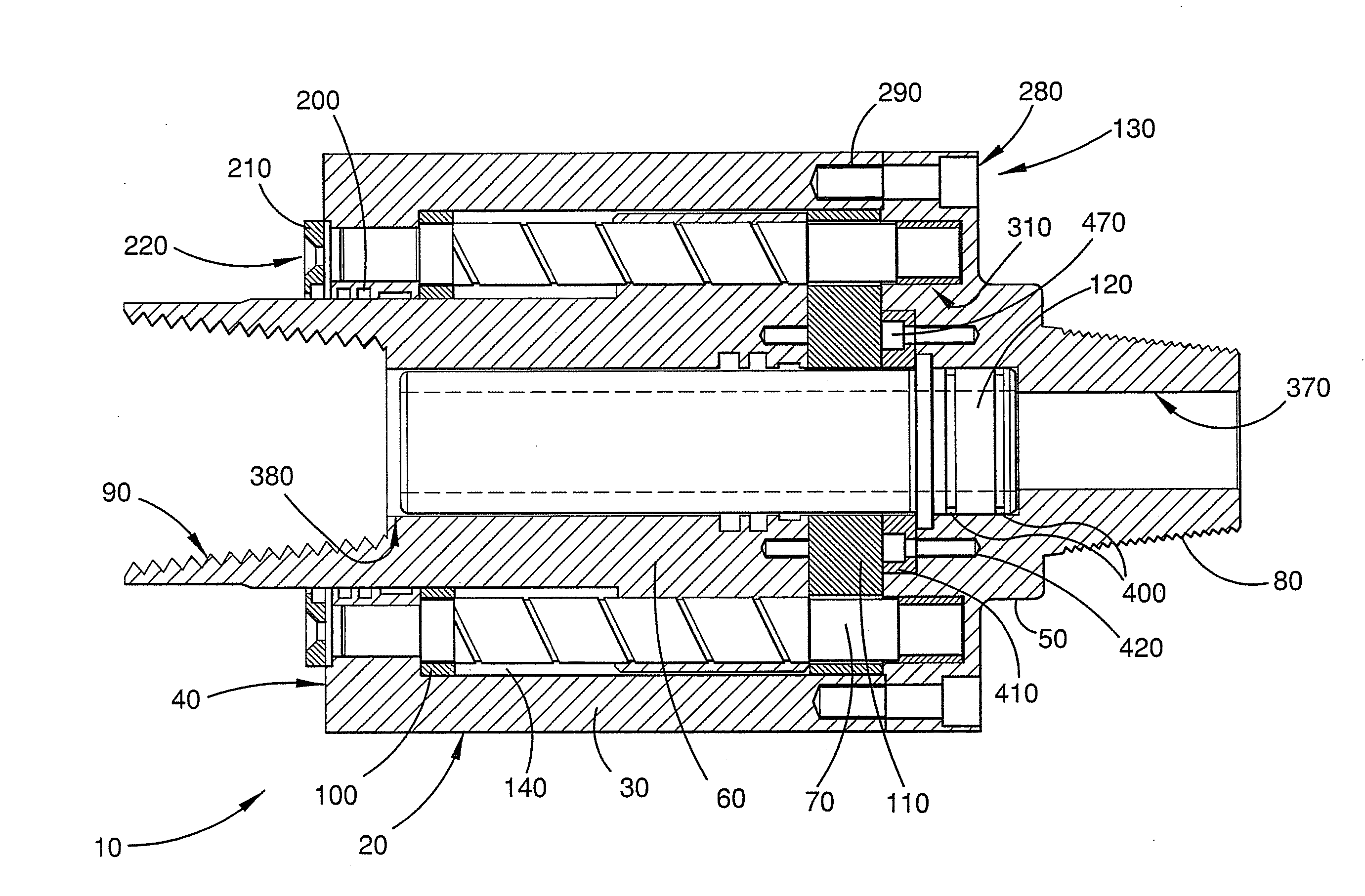
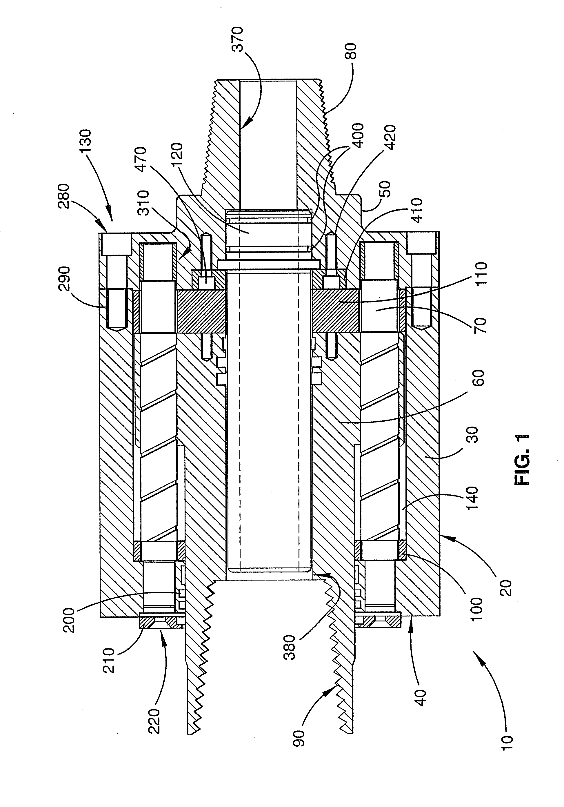
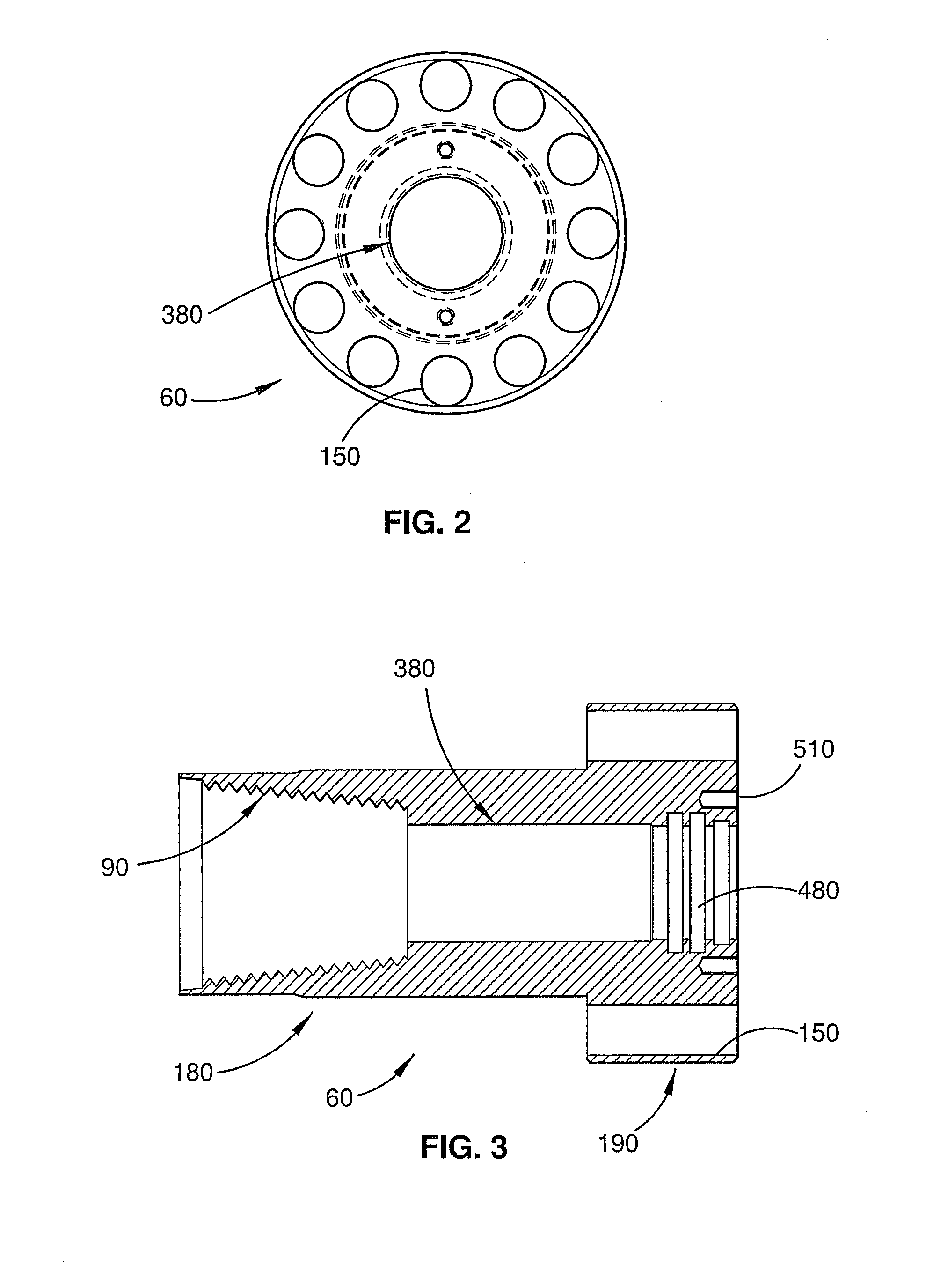
[0054]The cushion sub 10 includes two principal components: an input portion 130 and a piston 60. The input portion 130 includes an axially extending conical portion 270 with external threads 80 for receiving a rotational drive from a drill rig power head (not shown). Piston 60 includes an internally threaded tapered section 90 for receiving, and thereby transmitting drive to, a drill string (not shown) and thereby forms an output portion. As described in more detail below a passageway, partly defined by an air nozzle 120, axially extends through the cushion sub 10 for conveying air downhole.

[0055]The input portion 130 includes a cylinder body 20 and a head 50 which together define cylinder cavity 140. The cylinder body 20 is made up of a cylinder wall 30 and a back head 40. The piston 60 is axially slideable within the cylinder cavity 140. The input portion 130 also includes a circular array of twelve longitudinal drive pins 70 within the cylinder cavity 140. The drive pins 70 are ...


PUM


Abstract

A cushion sub 10 including an input portion 130 for receiving drive from a drive means, and an output portion 60 for transmitting the drive to a drill string. One of the input portion 130 and the output portion 60 including one or more guides 70. The other of the input portion 130 and the output 60 portion being engaged with the one or more guides 70 for transmitting the drive and arranged for relative reciprocating sliding movement along the one or more guides 70 between a first and a second limit of movements. At least one of the one or more guides 70 including a shoulder 500 adjacent at least one of and between the first and the second limit of movement to minimise adverse step formation as the at least one guide 70 wears. One of the input portion 130 and the output portion 60 may define a cylinder 20, 50 including first end wall 40 and second endwall 50. The guides 70 might be formed by drive pins 70. The drive pins 70 may be press fitted to the first endwall 40. The drive pins 70 may be mounted to the second endwall 50 via respective resiliently deformable mountings 310. The drive pins 70 may include a lubricating groove 400.

Description

FIELD OF THE INVENTION[0001]The invention relates to cushion subs.BACKGROUND OF THE INVENTION[0002]Cushion subs are used in mining applications for dampening vibrations transmitted upwardly through the drill string. The cushion sub is positioned between the top of the drill string and the power head and serves to protect the power head from vibrations, for example, vibrations generated by downhole hammering operations.[0003]U.S. Pat. No. 4,192,155 describes a cushion sub for connecting the rotary power head of a drill rig to a drill string. The cushion sub includes an outer housing 24 and a head in the form of cap member 40 which together define a cylinder. A piston in the form of mandrel 12 is received within the cylinder and is axially moveable therein. Guides in the form of axially extending splines 32 are spaced around the internal wall of the housing 24. The mandrel 12 includes axially extending external splines 22 which in use slide along the splines 32. Resilient cushion memb...

Claims


Application Information

Patent Timeline
Patent Type & Authority Applications(United States)
IPC IPC(8): E21B17/07E21B17/02F16D3/68F16D3/50F16D3/06
CPCE21B17/07F16D3/06F16D3/80F16D3/68F16D3/12
Inventor HAMPSON, EDWARD JAMESWILLIAMS, PAUL ANTHONYBRAUT, TONY LEE
Owner TPT PRECISION ENG
Why Eureka
Try Eureka