Formwork system

a formwork and system technology, applied in the field of formwork, can solve the problems of limiting the crane capacity of lifting gear, further complicating matters, and over-stressing of lifting devices

Inactive Publication Date: 2010-02-04
SENG TANG HANG +2
View PDF16 Cites 23 Cited by
  • Summary
  • Abstract
  • Description
  • Claims
  • Application Information

AI Technical Summary

Benefits of technology

[0011]The formwork system has a system of beams and bracings that may be fixed to the props to hold them in a fixed relationship with respect to each other, which also may be in turn adapted to carry the secondary beams and sheathings to enable the concrete to be casted and allowed to set more effectively. The beams provided in the system may be adjustable and thus may be flexibly extended according to the required length. The invention could be used as a soffit formwork for any rectangular floor shape of any size by extending the adjustable beam members or by inserting additional main frames to the formwork system when the floor size exceeds the maximum extended length of the beam members. In addition to that, the main frame is capable of providing a clear working space underneath at the center of the formwork system. Thus, this condition will enable the striking and transporting of the formwork system with the minimum of effort.
[0016]It is final object of the invention to provide a formwork system that can be repetitively used. The extensible surface of the formwork allows various sizes of concrete ceiling floor to be flexibly casted. The formwork system is also adapted to be lowered by appropriate jacking means and optionally having a plurality of wheels detachably mounted at the bottom of the props for transportation functions.

Problems solved by technology

Upstand beam or spandrel walls will further complicate matters and may need special adaption, such as folding legs.
The layout and size of the tableforms are usually determined by the shape of the soffit and the arrangement of columns, walls and access openings, together with the limitation of crane capacity of lifting gear.
Attempts to take the weight of the formwork while it is still in contact with the floor soffit can result in lifting devices becoming over-stressed and possible damage to the crane, formwork, falsework and structure.
The conventional tableform of consisting a lot of soffit parts is causing it to be a rigid construction structure that copious diligence is required to have it installed and dismantled.
It is also a limitation that said tableform containing a fixed top surface being not applicable to be further used for another time casting another ceiling floor.

Method used


Image

  • Formwork system
  • Formwork system
  • Formwork system

Examples


Embodiment Construction

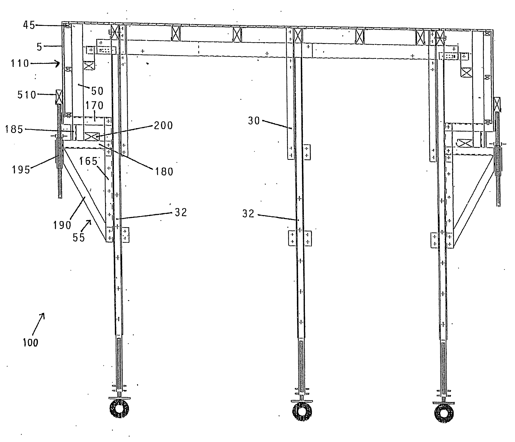
[0032]The present invention relates to a formwork system which is not only capable of casting typical concrete slab ceiling floor but also concrete ceiling floor which might constitutes concrete beams extended from the surface of the ceiling that further add supports to a building. It is therefore conceived a formwork system which is comprised of a main frame (100) to form a slab formwork under a concrete structural floor and at the sides of the formwork structure, pivotally connected side frames (110). While for the end of a spanned floor, the side frames (110) may further be assisted by end side frames (130), enabling a complete end concrete beam formwork to be erected.

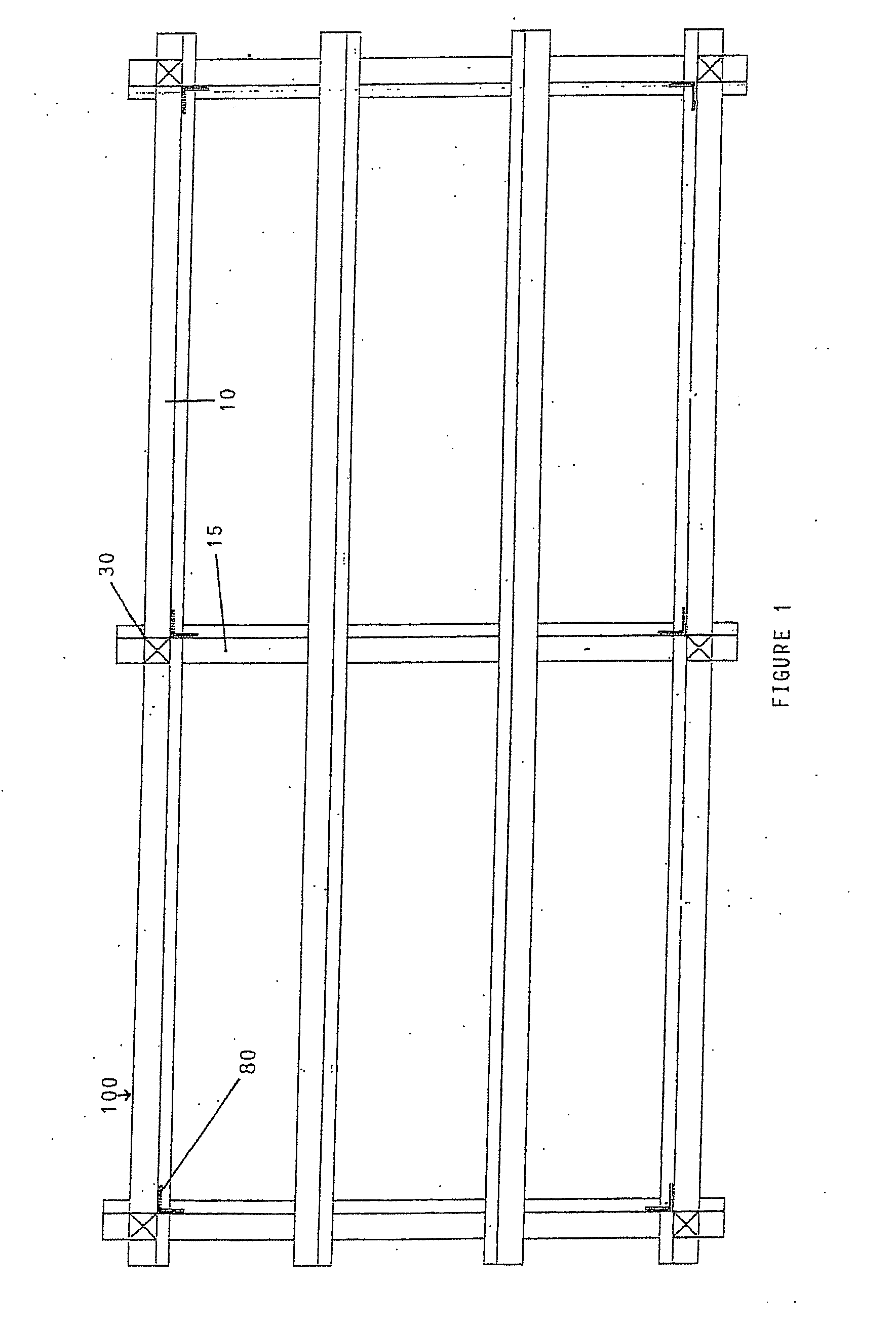
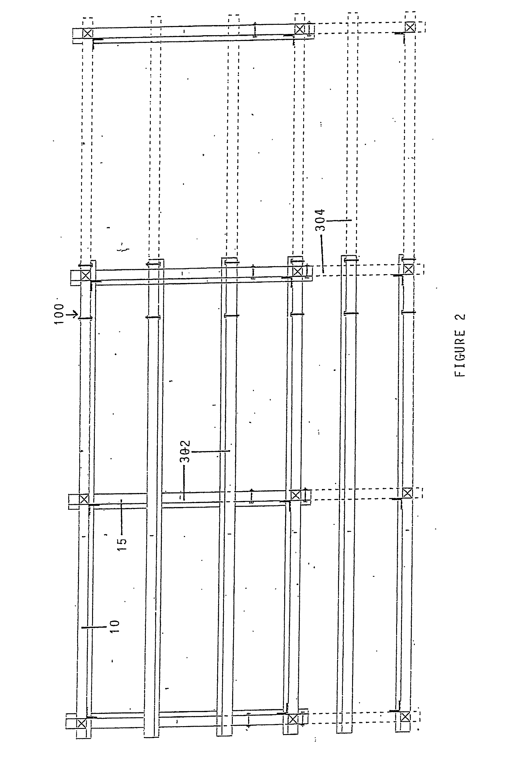
[0033]Referring now to the drawings, and particularly to the FIG. 1, there is disclosed in this view the formwork system as viewed from the top. The main frame (100) is comprised of a number of main props (30), a number of upper secondary beams (10) and a number of upper primary beams (15) which spans transversely b...


PUM


Abstract

A formwork system is provided for constructing a structural concrete floor, said formwork systems constitutes a main frame (100) forming a concrete slab structure, a plurality of side frames (110) each movably mounted at the edge of the main frame (100) for forming a concrete beam formwork structure, and a plurality of retainers mounted at the edge of the main frame (100) for supporting below the side frames (110) and jacking means for raising and lowering the formwork system. The side frame (110) being movable enables the formwork system to be effectively detached from a casted structural floor having concrete beams extended therefrom. The formwork system is also extricable on site after fabrication of the concrete ceiling slab floor and concrete beam.

Description

FIELD OF INVENTION[0001]The present invention relates generally to the field of formwork for building construction, and more specifically to a proprietary formwork system which is designed to be struck in one piece for the casting and setting of concrete forming a floor at one level, and carried to a higher level above said floor for further casting and setting of concrete forming another floor.BACKGROUND OF THE INVENTION[0002]Formwork is a temporary structure that was erected for the purpose of allowing the wet concrete to be retained and shaped into desired shape and form. Its structure usually consists of sheathing, beams, walings, ties and any other supports that are necessary to ensure that the formwork structure is stable and rigid. It must also be safe for any worker working on or near the formwork.[0003]In order to ensure the stability and rigidity of the formwork, it is important that sufficient longitudinal, transverse and diagonal bracings are provided. In addition, conti...

Claims


Application Information

Patent Timeline
Patent Type & Authority Applications(United States)
IPC IPC(8): E04G11/48E04G21/10
CPCE04G11/02E04G11/40E04G11/36
Inventor SENG, TANG HANGTOW, TANG HANGCHYAN, TANG HANG
Owner SENG TANG HANG
Why Eureka
Try Eureka